Wiring The Schematic
Intuitive tools are what sets Altium Designer apart from its competitors. These tools allow novice users to develop electrical circuits at the professional level, without the need for in-depth training or knowledge. The development of connections starts with the schematic. These connections are needed to determine the relationship between the components and show CAD which component pins should be connected. Each drawn connection on the schematic sheet will become a complete metal connection on your PCB, so use the utmost care when designing and placing connections. All created connections will be transferred to the PCB after project validation. However, competent setup of the schematic will save you from possible errors and save you time and money. Now let's add the electrical connections to the sheet.
Place Wire ( ) is the main tool for making schematic connections. You can easily access it using the Active Bar or Place > Wire from the main menus or by using the Ctrl+W hotkey. Let’s add a couple of connections.
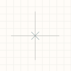
Run the Place Wire tool using any of the above features. After activation, a crosshair is attached to the mouse cursor, indicating that the placement tool is ready for use.
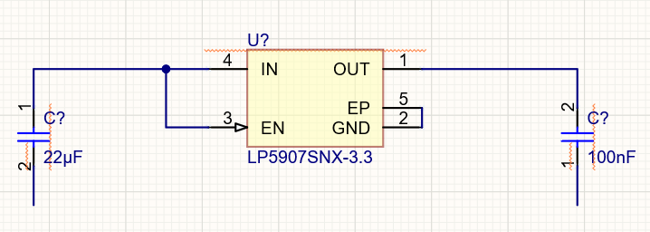
Zoom to components that are located at the bottom part of the schematic. We will connect them first. Hover your mouse above pin number 1 of LP5907SNX-3.3. While hovering, you will see a small blue crosshair indicating that the wire is snapped to the component pin. Click to start placing a wire.
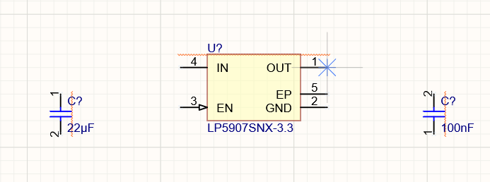
Warning: You should always connect the wires ONLY after you see the blue crosshair; wire placement without snapping is guaranteed to cause problems.
Route the wire to pin number 2 of the nearest capacitor. Click to place the wire (i.e. connection).
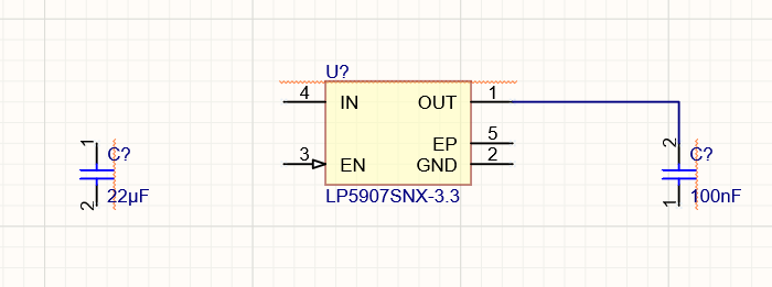
Tip: You can press the Spacebar to create an elbow in the wire.
Place two more connections at the left side and connect pins number 2 and 5 of the LP5907SNX-3.3 component as shown below.
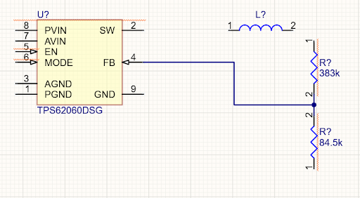
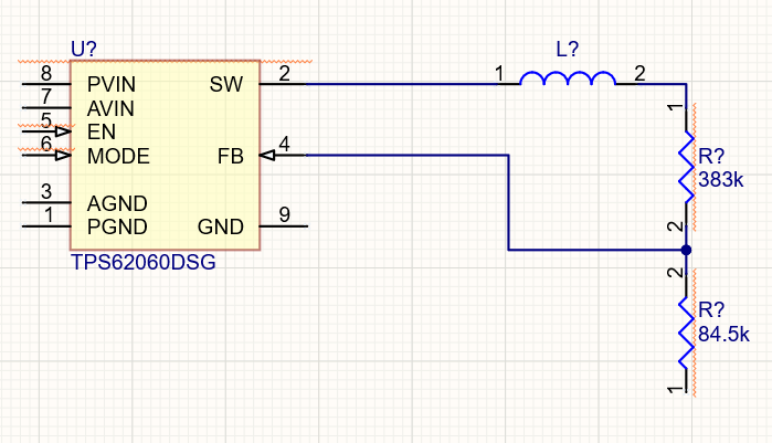
It is not always possible to place the connection with only two clicks on the pins being connected. It may be necessary to add intermediate points at the wire route, more accurately drawing the route of the wire. Move the cursor to the TPS62060DSG component. We need to connect pin number 4 to the voltage divider of the two resistors to the right of the component. While performing wire placement, you can click to fix the already-placed wire segment and continue wire placement relative to this point. Place wires as shown below.
Connect the placed wire to the resistors making a wire cross-section.
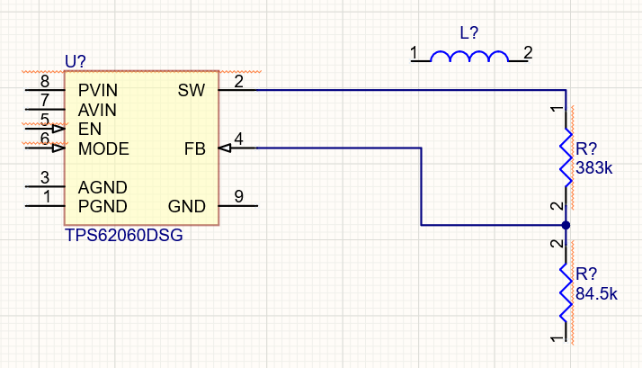
Connect pin number 2 of TPS62060DSG to pin number 1 of the resistor to the right.
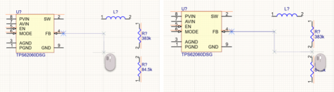
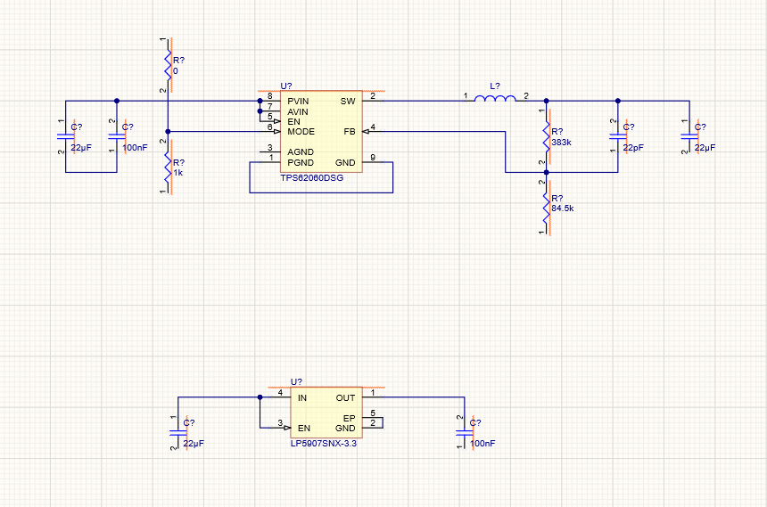
You can insert a component on the placed wire to connect it to this net. Select the inductance coil and put it directly on the wire that was placed in the previous step. The software will automatically cut the unnecessary wire segment and connect the placed component to the net.
Now you have learned all the basics you need, which allows you to complete the wiring of this schematic. Finish wire placement referring to the figure below. Remember to pay attention to the wire cross-junctions!
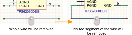
There are times that a previously drawn connection needs to be deleted. Altium Designer supports the complete removal of the wire (the entire part between the pins is removed), removal of the conductor segment, or wire cutting. To remove the entire conductor, click to select it then press Delete. To delete the selected segment, click on a wire to select it then click on the required wire segment. Red dots will appear at the edges of the wire segment, indicating the part that will be removed. Press Delete to delete it.