Creating Net Classes
A Net Class is a logical collection of nets of similar functionality that can be used as a basis for creating a targeted design rule. Net classes are especially convenient because they can be highlighted in a separate color on the board, therefore, increasing the traceability and the flexibility to set up rules for them. It is not a secret that, for the sake of reliability, the power supply conductors need a larger width of trace than ordinary conductors. Our drone must be perfectly reliable, so let's add a new class for power circuits. The rule will be created in the future.
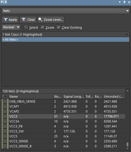
Open the PCB panel. Select Nets from the top drop-down menu. After the selection, the PCB panel is configured to work with the nets. Select <All Nets> in the Net Class list to show all nets in the Nets list below.
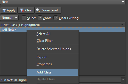
Right-click on <All Nets>. Select Add Class from the context menu. The Edit Net Class dialog will open.
Tip: It is not necessary to right-click precisely on the <All Nets> string; you can open the context menu by right-clicking anywhere in the region. You can also create a Net Class by selecting Design > Classes from the main menus.
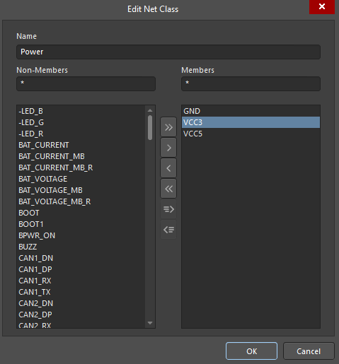
Now we need to add a Net Class that will contain heavy-duty power nets in order to create design rules. In the Edit Net Class dialog, enter Power in the Name field. This will be the name of a Net Class.
Select nets GND, VCC3, VCC5 from the netlist by selecting GND, holding the Ctrl button then selecting VCC3 and VCC5. Click on the > to add the selected nets to the Net Class. As a result, the selected nets have been moved to the right-hand region. Click OK to create the net class with the specified net class members.
Tip: You can use the search field above the net list for faster net search and filtering.
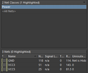
As a result, in the PCB panel, there is a new net class with the name Power that contains only power nets. Click on the name Power to display the nets that belong to this class. We can also see information about nets for high-speed routing. You can customize columns by right-clicking in the Nets region then selecting Columns from the context menu and enabling/disabling the desired columns in the sub-menu. By right-clicking in the different regions, you can interact with the net class as a whole (Net Class(es) region), or with individual nets (Nets region). For example, you can change the visibility of connections (Connections > Show/Hide) or choose the color of connection lines for better PCB routing planning (Change Net Color).