

Schematic Port Placement
Each drone's schematic sheet performs a specific function so we need to create sheet symbols to understand the interaction between the drone modules. In order to present the schematic sheet in the form of a sheet symbol and to set the connections between all schematic sheets of the project, we need to place and configure special sheet symbols on schematic sheets named Ports. Ports on the schematic should be connected to input and output signals, which will interact with the rest of our drone's functional parts. The name of the port defines the connection name that will be displayed during sheet symbol placement and interaction. A significant part of the ports has already been placed in our drone project - all we have to do is finish placing the ports on one of the project sheets. Let’s do that now!
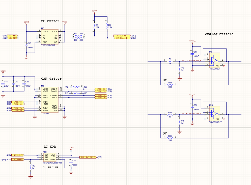
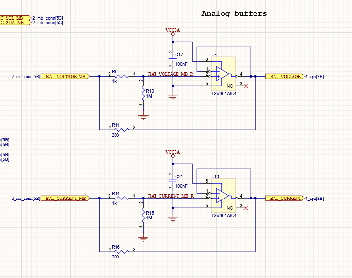
Open the 7_can_rc_i2c_analog.SchDoc sheet. There are two amplifiers on the right side of the sheet located under the Analog buffers text. These amplifiers are required for transforming the current and voltage coming from our drone's motherboard to meet the supply requirements of the CPU components group. It is important that the connections to these amplifiers be present on the sheet symbol.
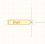
Choose Place > Port from the main menus or select  Port from the Active Bar to activate the Port placement tool. After activation, a crosshair with a port will be attached to the cursor.
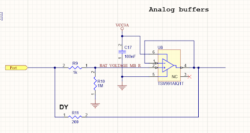
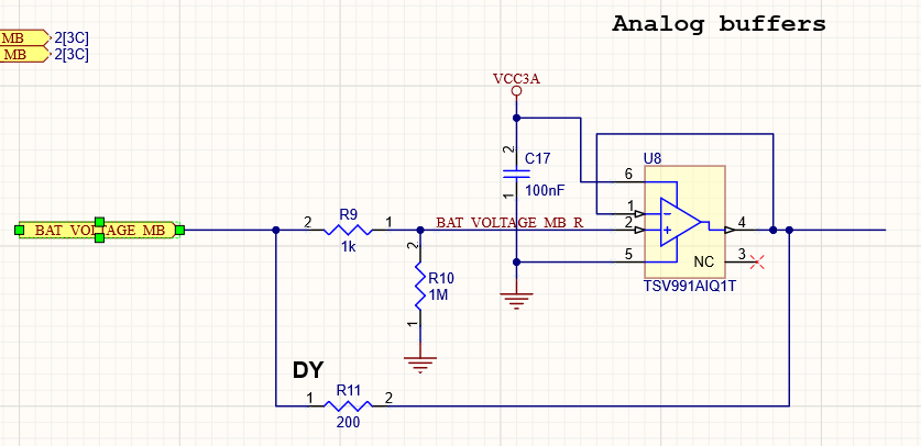
The mechanics of the port placement is similar to placing other objects on the schematic, except after placing the port, you will need to define the length of the port symbol. To do this, hover the mouse at the top left track of the Analog buffers group. When a blue cross appears (denoting the port placement is valid), click once. After the first mouse click, your port is partially placed; you will need to move the mouse left and right to determine its length. Once the length is correct, click again to finish port placement. Your port should now be placed as shown in the figure below.
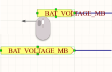
Right-click to exit port placement. We need to configure the placed ports, in particular, to define the name and set the correct I/O type. Click to select the top left port then open the Properties panel. In the Properties region of the panel, enter BAT_VOLTAGE_MB in the Name field and use the I/O Type drop-down to select Input. The signal direction arrow is now directed towards the amplifier. It is likely that the port name will not be visible. To fix this, select and drag the green square on the left side to lengthen the port.
Tip: The port symbol’s width and height also can be changed by defining it in the Properties panel.
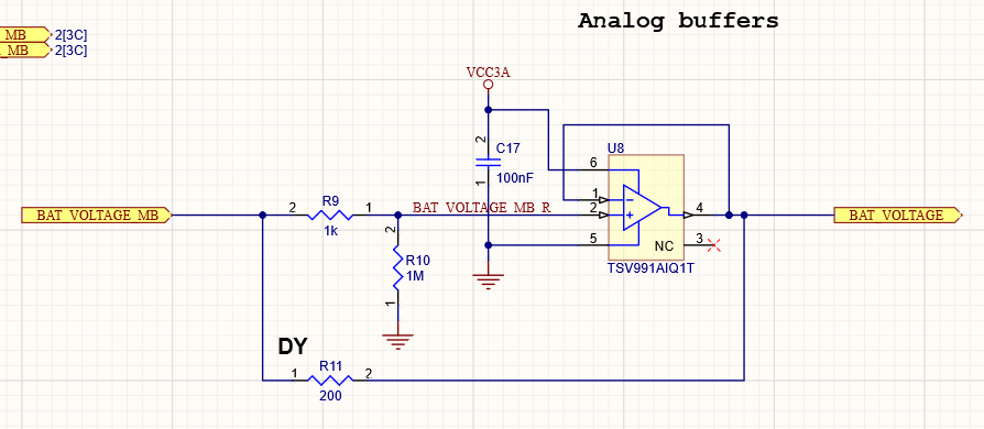
Now we need to define the output signals on the right side. Unlike the previous approach, we'll set up ports “on the fly” using the Properties panel and the pause feature. Run the Place Port tool again then press Tab to pause placement and open the Properties panel.
In the Properties section of the panel, enter BAT_VOLTAGE as the Name and define the I/O Type as Output. The signal direction arrow is now directed at the other direction as if the signal were coming out of the amplifier. This indicates the output signal. Press the Tab key again to resume placement. Now, the crosshair is attached to the left side of the port. Hover the port at the top right track then click to place the port. After the first click, you need to define the width of the port so that the name is fully enclosed in the symbol. Once you have determined the width, click again to finish port placement.
Now let’s set the ports for the lower group of components. We need to define the BAT_CURRENT_MB port for the input signal of the group and BAT_CURRENT port for the output signal. You can do this by placing the ports as was done with the BAT_VOLTAGE ports group, or by using the following (and quicker) method.
Select the BAT_VOLTAGE_MB and BAT_VOLTAGE ports. Press Ctrl+C to copy them to the clipboard.
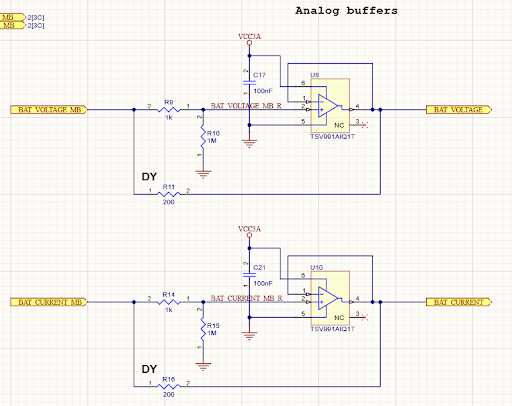
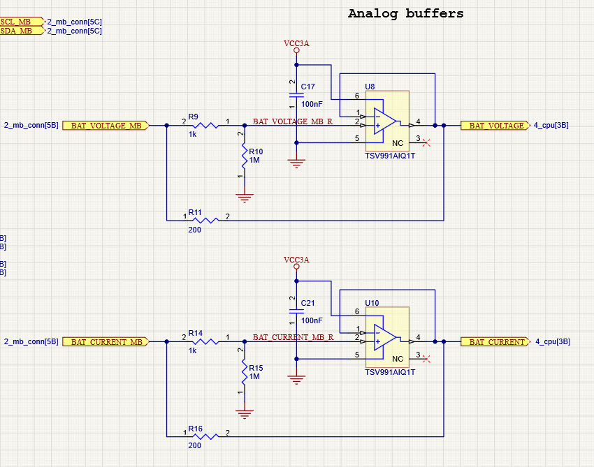
Press Ctrl+V to paste the copied ports. Place them as shown in the figure below, paying attention to the snapping crosshair. This way of copying saves from needing to configure the ports.
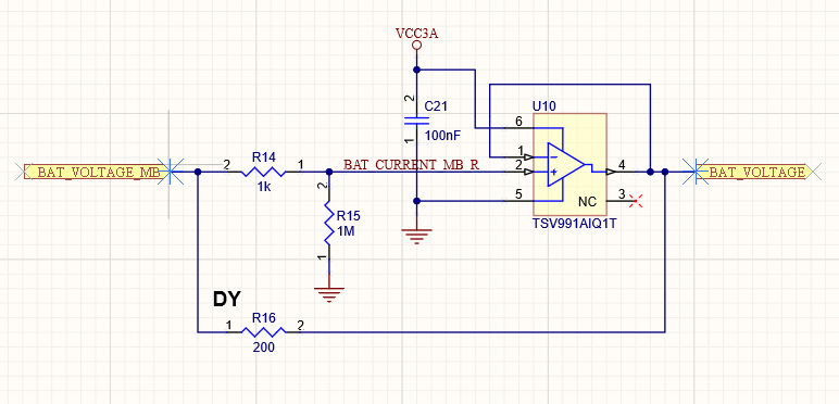
Select the lower left port. Define its name as BAT_CURRENT_MB in the Properties panel. Set the name BAT_CURRENT for the lower right port. The result of this step is shown in the figure below.
Tip: Ports can also be rotated in any direction. This is not necessary for the purposes of this guide, but may be required for other projects. Use the Spacebar to rotate ports.
As you may notice, other ports located on this sheet have a specified reference to another part of this device, which will simplify the interconnections placement on the sheet symbols in the future. Let’s specify reference part parameters for the ports we created. Select Reports > Port Cross Reference > Add To Project from the main menus to automatically define the ports reference parameters for all ports that are present in the project.
Select the placed ports and open the Parameters tab of the Properties panel. A new locked parameter named CrossRef has been defined for all created ports. Let’s change its font. Select the CrossRef parameter on the panel then click the font text at the bottom of the Parameters region. Use the Font Settings drop-down to select Arial as the font.
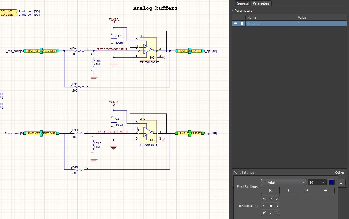
Move the parameters slightly so that the parameter names do not touch the port symbols as shown in the figure below.
Now that all the ports are placed, nothing should prevent the sheet from being represented as a sheet symbol.