Synchronization with Schematic
Whether you're transferring a captured design to a new PCB for the first time or making changes to an existing design on either the schematic or PCB side, you need a way to keep the two sides synchronized. Altium Designer includes powerful design synchronization capabilities that simplify the task of keeping the design synchronized, allowing you to keep your focus on the creative aspects of the design process. All components with parameters, directives, and constraints are transferred from the schematic to the PCB during the synchronization process. Synchronization is only available after a successful project validation. Let’s synchronize our schematic with the newly created PCB.
Make sure the PCB is active and open. Select Design > Import Changes From Kame_FMU.PrjPcb from the main menus to open the Engineering Change Order dialog.
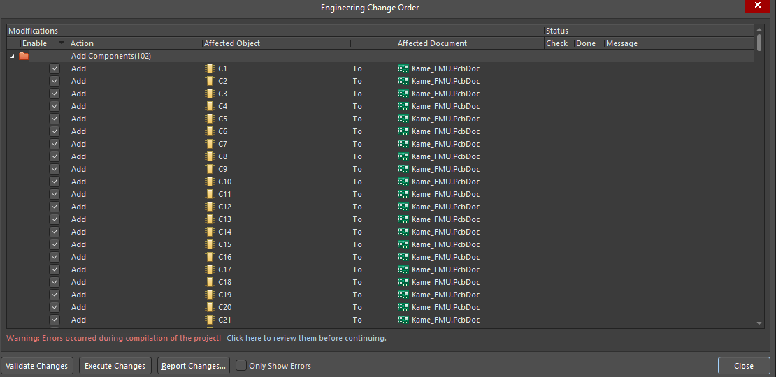
The grid of this window lists all types of objects added to the PCB: components, nets, component classes, net classes, differential pairs, rules, etc. When synchronization is started, the comparator will translate every object placed on the schematic to the PCB and show its status. Statuses and their descriptions are as follows:
 - An error has occurred and the object has not been added to the PCB. A description of the error is written to the right of the symbol and you need to go back to the schematic to fix it.
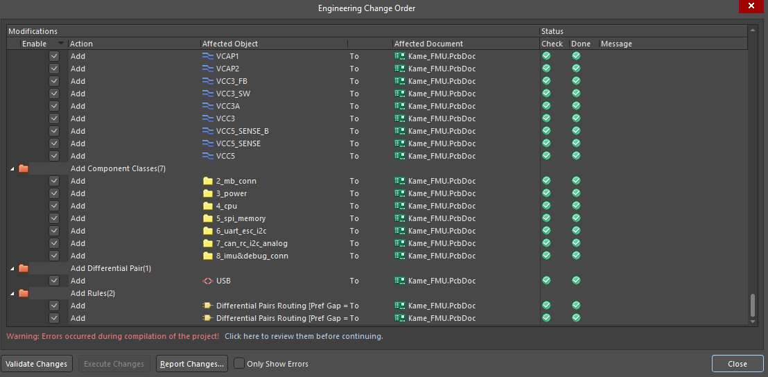
 - No errors occurred during synchronization and the object has been added to the PCB.
Click Execute Changes at the bottom of the dialog to start the synchronization process.
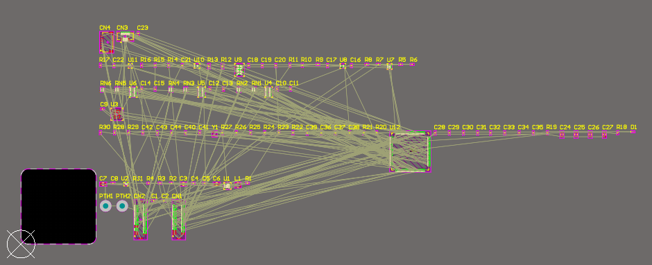
As a result of the synchronization, you should see the following: