Schematic Components Placement
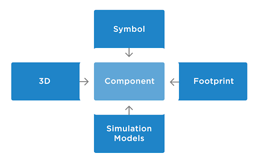
Everything is now ready for component placement. The foundation of every created design is based on its components. Think of them as small yet very powerful bricks that are used to create the finished product of a perfectly working device. Components in the real world are tangible objects that can be visually differentiated from each other. However, in the world of PCB design, the same components should be presented in a CAD-understandable format. Therefore, the virtual component should not only completely correspond to real parameters, but also have a unique set of additional models. Component representation differs for each stage of design. On the schematic, components are presented in the form of a symbol, on the PCB in the form of a footprint, and on the drawing in a contour with real dimensions. In Altium Designer, all this is presented in an incredibly convenient format of cloud libraries. Additionally, you can use the Manufacturer Part Search panel to add components (that are not presented in your cloud library) to the schematic on-the-fly using Altium Designer’s Octopart integration. This allows you to see the prices and availability of any component from suppliers in real time! Very convenient, isn't it? In this guide, we have prepared a cloud library for you so you don't even have to search and add components! Let’s get started!
You will no longer have any trouble finding your required components using the Altium Designer cloud library so nothing prevents you from starting to place components on your schematic sheet. In this chapter, we will create a power supply system for our drone. Let’s begin!
If you are not using Altium Designer cloud technology, you can still follow this guide. To do so, you need to use Kame_FMU.SchLib local library that included to the project you have downloaded in chapter 2.1. Select this library in the top dropdown menu of the Components panel. You can now continue with this guide using the local library.
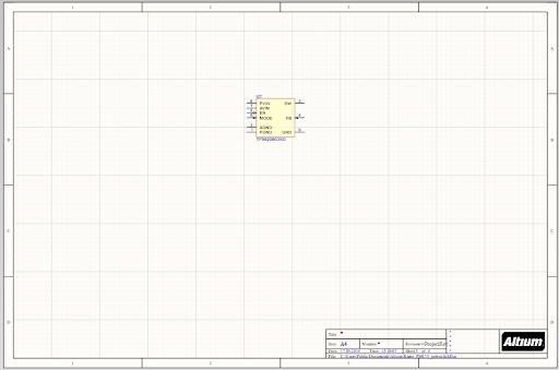
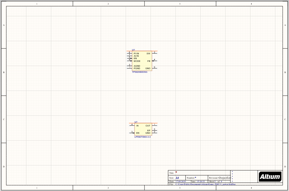
Open the 3_power.SchDoc schematic document from the Projects panel. An empty sheet opens that we will populate.
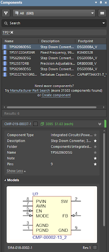
Let's place the power ICs. Find the IC named TPS62060DSG in the Components panel.
There are several ways to place components on the schematic sheet:
-
Place your cursor over the desired component in the list of components. Click and hold the left mouse button. Drag the component to the schematic sheet while holding the left mouse button. Release the left mouse button at the location you want to place the component. The component will automatically be placed at that location. This is the best and quickest way to place a single component.
-
Double-click on the desired component in the components list to attach the selected component to the mouse cursor. Hover the mouse at the desired placement location then click the left mouse button to place the component. Once placed, the placement tool does not stop working. This allows you to place several identical components. To exit placement mode, press the Esc key or click the right mouse button.
-
Right-click on the desired component in the components list then select Place from the drop-down menu. Place the component as stated in the section above.
Place the component TPS62060DSG in the middle of the top half of the schematic sheet in one of the methods described above.
Use the same approach to place the component LP5907SNX-3.3 in the middle of the bottom half of the schematic sheet.
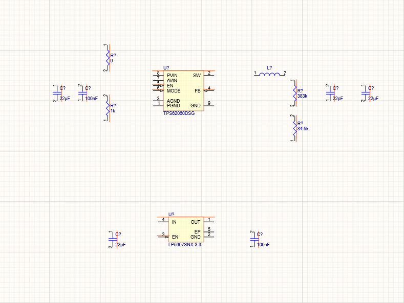
Now we have two main components that will provide excellent PDN work for our drone. However, these components will not work correctly without the additional passive components called the device decoupling. These passive components are needed to properly configure and limit component performance. Let’s add them.
Find the components below in the Components panel and place them on the schematic as shown in the below image using any method described above.
VLS252010HBX-2R2M-1
Capacitor 22µF +/-40% 16V 0805
Capacitor 100nF +/-20% 10V 0402
Capacitor 22pF +/-10% 50V 0402
Resistor 383K +/-1 % 0402 63 mW
Resistor 1K +/-5 % 0402 63 mW
Resistor 84K5 +/-1 % 0402 63 mW
Jumper 0402
Tip: You can quickly search required capacitors or resistors using a *value* search request, e.g., *22pF* or *84K5*. After placement, your sheet should look as shown below.
After placement, your sheet should look as shown below.