Schematic Grids and Preferences
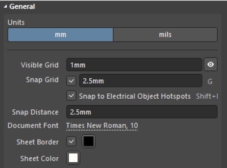
Before developing a scheme, you should be familiar with the definition of the grid in Altium Designer. The schematic editor is based on the principle of working with the grid, meaning all placed objects of any type are placed at the intersection point of the grid lines with a certain distance. Altium Designer allows you to configure visible grids for ease of document navigation and snap grids for precise component placement and wiring. Visible grids appear whenever the zoom level allows them to be sufficiently spaced and are displayed as either lines or dots. The intersection point where you can place an object is set up with snap grids. You can configure the grid settings at any time in the General region of the Properties panel.
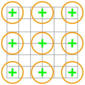
An example of the visualization of snap points is shown in the figure below. The gray lines show the visible schematic grid with a 1mm step. Orange circles show cursor anchor points depending on the settings of the Snap Grid.
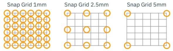
By default, Altium Designer has preconfigured snap grids with 1mm, 2.5mm and 5mm grid spacing, which can be switched in any editor by pressing the G hotkey button at any time. You can set your own values on the Schematic - Grids page of the Preferences dialog (accessed by clicking the  icon at the top right of the design space then navigating to Schematic > Grids). Right-click in the grid list of the measurement unit you need. The type of grids used depends on the unit of measurement selected in the Properties panel. The current grid size can be seen in the lower-left corner of the design space. We recommend using a smaller grid size (e.g., 1mm) to draw the component symbols more accurately and precisely, and 2.5mm or 5mm grid (depending on the density of the schematic component placement) for the component placement and connections.
The General section of the Properties panel also allows you to set the Snap Distance at which the cursor will be automatically attached to the anchor point. In most cases, the Snap Distance value must be equal to the Snap Grid size to avoid placing objects outside of grid intersections. In certain cases, the Snap Distance value can be reduced (1/2 or 1/4 of the Snap Grid size), but it should not be larger than the Snap Grid size. For example, the Snap Grid is configured at 2.5mm and the Snap Distance is configured at 1mm. In this case, the crosshair will automatically be attached to the grid intersection point, which is less than 1mm away. The illustration below shows the possible snap points for this configuration as green crosshairs and the Snap Distance as orange areas.