Schematic Documentation Outputs
In this guide, we will set up an export of the schematic sheets.
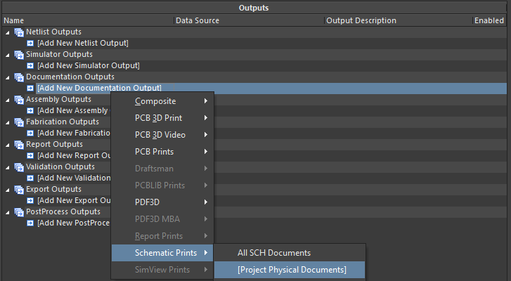
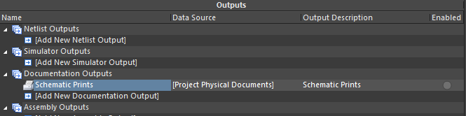
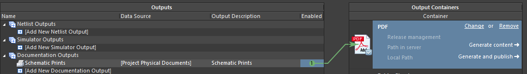
Click [Add New Documentation Output] in the Documentation Outputs section then select Schematic Prints > [Project Physical Documents] to add all physical schematic documents to the output. The term "Project Physical Documents" refers to the physical or compiled view of the schematics. In the schematic editor, this corresponds to the validated document(s) that appear after the validation of a document/project. After selection, a new Schematic Prints line item appears. Now we need to configure this output, define the output container and enable it.
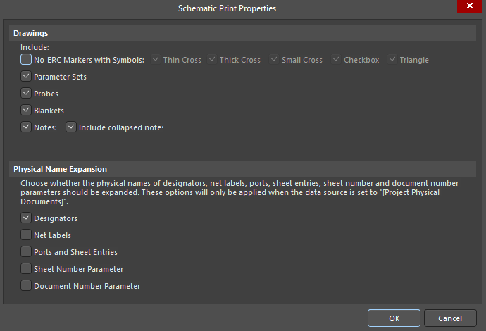
Double-click Schematic Prints to open the Schematic Print Properties dialog in which you can configure the print properties of the schematic(s). We want to exclude the display of all No-ERC markers on the printed file of our schematic sheets, therefore, uncheck the No-ERC Markers with Symbols option to hide No-ERC markers with all symbols from all schematic sheets. Press OK to apply the changes
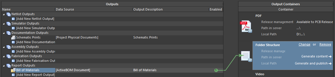
Select PDF in the Output Containers region of the OutJob editor. In this region, you can define the output format of the exported document and, if necessary, combine some documents into a single PDF file by enabling them into a single container. The Folder Structure container is a unified format for uploading files in its own format (e.g., a 3D model will be exported in STEP format; BOM files in .csv or .xls, etc.). Click the Enable circle associated with Schematic Prints. Now, when all files are exported, the schematic sheets will be uploaded in PDF format.
Let’s add an ActiveBOM document. Click [Add New Report Output] in the Report Outputs section then select Bill of Materials > [ActiveBOM Document].
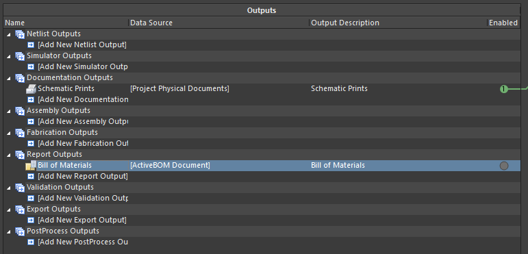
Select Folder Structure in the Output Containers region. Click the Enable circle associated with Bill of Materials.