First Steps With Interactive Routing
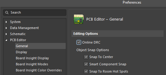
According to our surveys, users spend about 40% of their time on routing and track optimization as part of the PCB design and most errors are made during this stage. With the help of special algorithms and tools, Altium Designer not only significantly reduces the time spent routing (with the help of the ActiveRoute function) but also reduces the probability of errors due to Online DRC - real-time verification of the project's compliance with the rules. It prevents new errors by maintaining all the specified restrictions and displays violations that exist in the project. It is recommended that the Online DRC option is enabled during the entire routing process. To enable the option, open the PCB Editor > General page of the Preferences dialog then enable the Online DRC option.
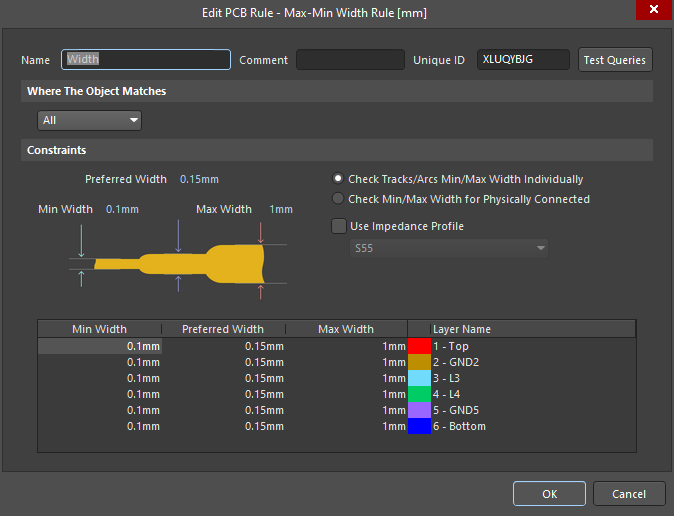
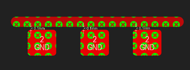
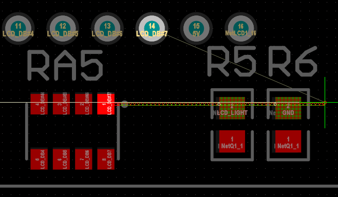
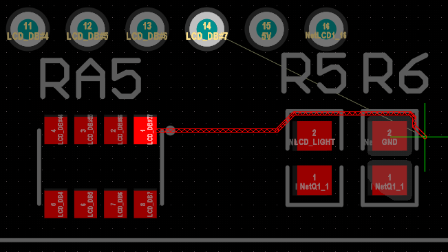
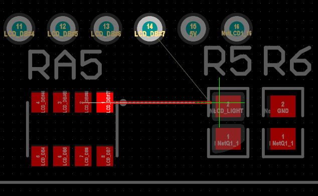
The figure below shows an example of Online DRC operation. In this case, the clearance between the objects violates the rules. You can see which rule has been violated by right-clicking on any violating object then selecting Violations. Click on a violated rule in the Violations sub-menu to be redirected to the rule settings.
The Properties panel also adapts while routing. When the Interactive Routing tool is running (Route > Interactive Routing), the panel displays settings and options that may be required during the routing process.
When the Interactive Routing tool is running, the Properties panel displays the following functional regions:
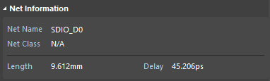
Net Information - This region displays information about the selected net or the net that is being routed. In this region is the name of the current net, its net class, length and the delay of the transmission line.
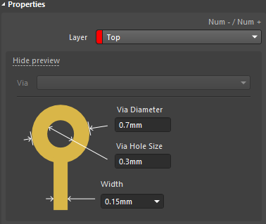
Properties - This region displays the currently selected routing layer and the editable parameters of vias and tracks used.
Interactive Routing Options - This region is used for the flexible customization of track routing according to your specific needs. Options are described below.
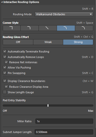
The Routing Mode drop-down is used to select one of the following routing modes.
- Ignore Obstacles: The Interactive Routing tool ignores any obstacles.
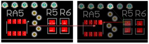
- Walkaround Obstacles: The Interactive Routing tool bypasses obstacles without moving them.
- Push Obstacles: The Interactive Routing tool pushes every obstacle on the routing path according to the rules.
- HugNPush Obstacles: The Interactive Routing tool bypasses obstacles and pushes them out if the track placement is impossible.
- Stop At First Obstacle: The Interactive Routing tool stops at the first obstacle at the track route.
Corner Style - This region allows you to choose the track corner style between five different styles.
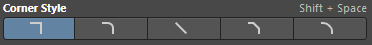 - 90 degrees corner
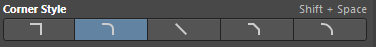 - 90 degrees corner with rounding
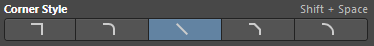 - any angle routing
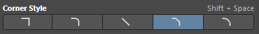 - 45 degrees routing
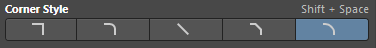 - 45 degrees routing with rounding
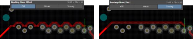
Routing Gloss Effort - This region is used to adjust the post-processing intensity of the “Gloss” effect of the track being routed. This effect is intended to form a smoother track without unnecessary and sharp corners while routing. It is recommended to set this parameter to Weak or Strong to obtain high-quality routing in real-time, which will help to not waste time later when optimizing the topology of the completed PCB.
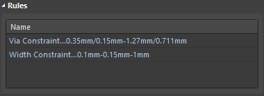
Rules - This region displays the entire set of rules applicable to the tracks being routed. Every rule in a set can be quickly edited by clicking on it.