

Using Power Ports
Almost every device is powered from the outside, whether it's a battery, a power cable or some other type of power device. The components are connected to a specific power supply net and connected to the ground (a net without current) to ensure potential differences, therefore, you need to define all power connections in your schematic. Modern devices can have several different power supply nets (3.3V, 5V, 1.2V, etc.,), as well as several isolated ground layers (separation of analog and digital ground). Each power port is represented as a graphic element with a name that characterizes the power net and is linked to all the schematic sheets.
The components that we have placed on this schematic sheet are step-down current converters. In other words, when supplied with 5V current to the input, they produce the 3V current needed to power the other components of our drone. In Altium Designer, the power ports are placed using the Power Port tool ( ). You can easily access it in the Active Bar or select Place > Power Port from the main menus.
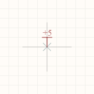
Run the Power Port tool. After running the tool, a crosshair with a power port is attached to the cursor, indicating that the tool is ready for use.
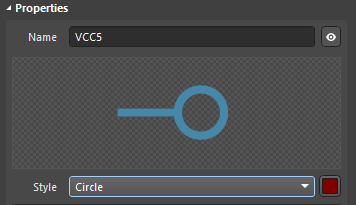
We need to configure the power port before placement. Press Tab to pause the power port placement. In the Name field of the Properties panel, enter VCC5 - this is the name of the input voltage. Select Circle from the Style drop-down menu. Press Tab again to resume power port placement.
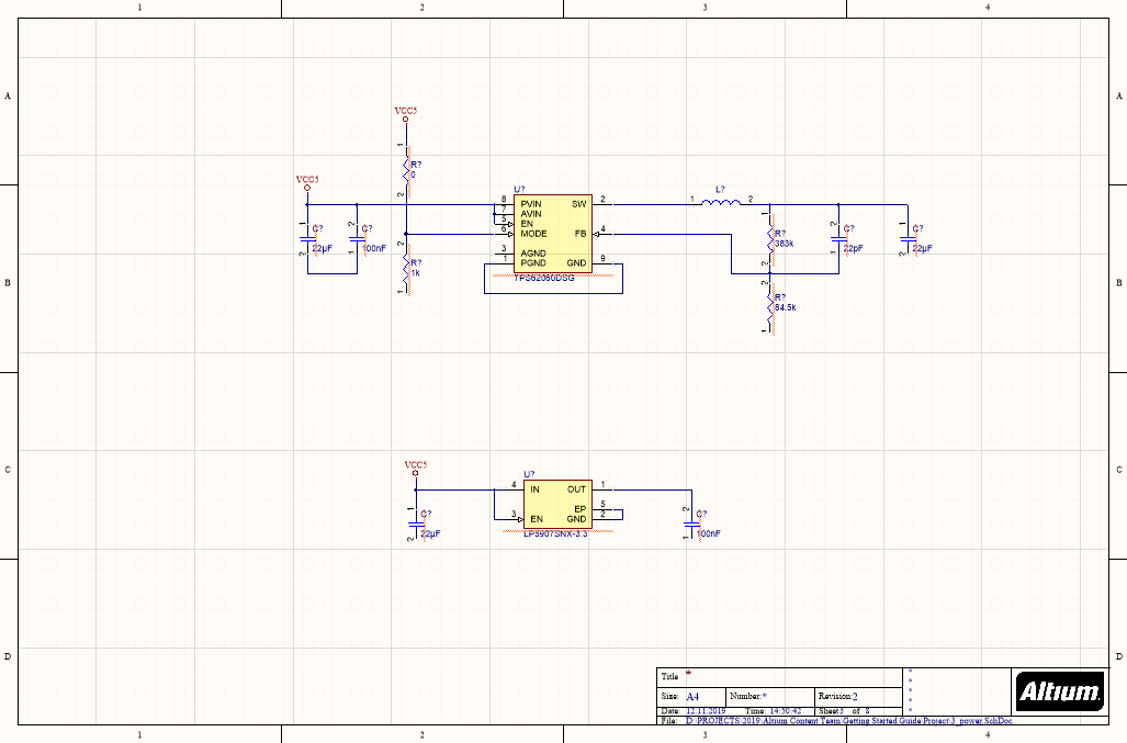
Place three VCC5 power ports at the positions shown in the figure below.
Tip: You can drag a power port in the same way as a component. It is recommended to place power ports several grid steps from the required connection point and wire them manually.
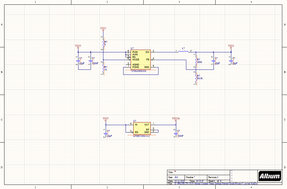
Now we need to place power ports that will represent output current for our converters. Using the approach described above, place power ports VCC3 and VCC3A as shown below.
Now we need to place ground ports. Component TPS62060DSG requires a connection to signal and power ground nets to avoid unnecessary plane noise in the power distribution network. That is not a problem with Altium Designer!
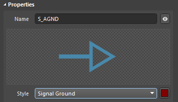
Press Tab to pause placement. In the Name field of the Properties panel, enter S_AGND. Select Signal Ground from the Style drop-down menu. Press Tab again to resume port placement.
Place two S_AGND power ports at the positions shown in the figure below.

Tip: Use the Spacebar to rotate the power port.
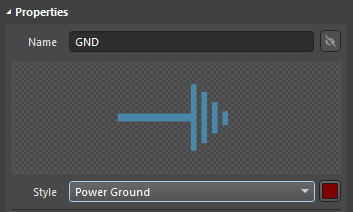
The final step of power port placement is to place power grounds. Press Tab to pause placement. In the Name field of the Properties panel, specify GND - this is the common name of the ground net. We do not need to show the name of the ground net, so click the visibility icon ( ) to hide the net name. Select Power Ground from the Style drop-down menu. Press Tab to resume port placement.
Warning: You should always connect the wires ONLY after you see the blue crosshair; wire placement without snapping is guaranteed to cause problems.
Place seven GND power ports at the positions shown in the figure below.
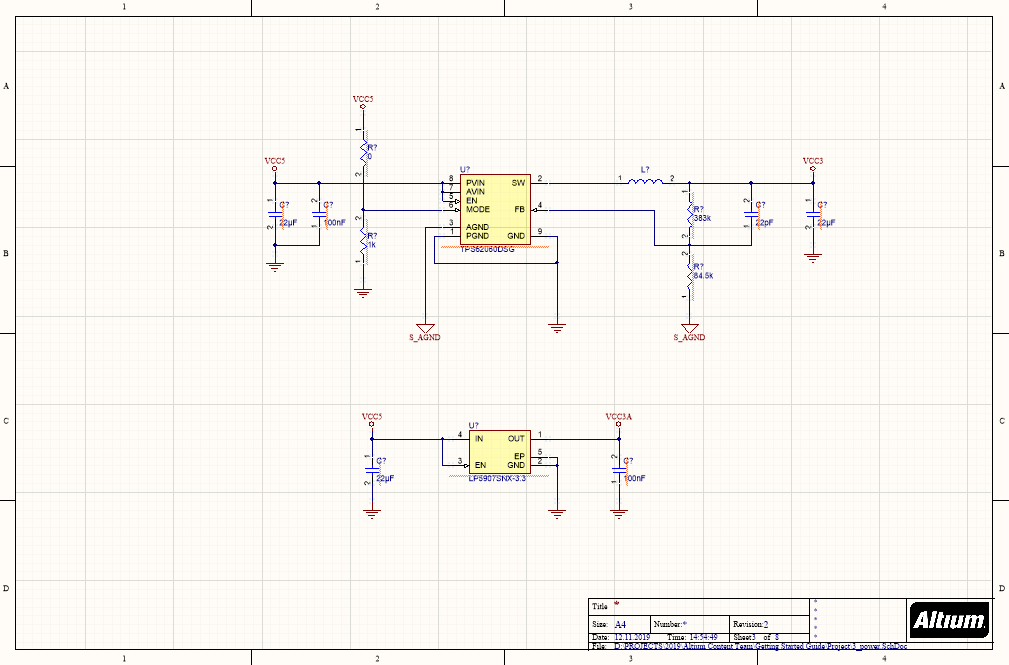
At this point, the placement of the power ports on this schematic sheet is complete. That was simple enough, right?