Interaction with Projects
The creation of any electrical device begins with the design of an electrical circuit that represents all the components and the connections between them. As part of this guide, we will create a schematic sheet with a power management system for one printed circuit board of the drone.
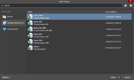
Open the project in which the design will be performed. Select File > Open Project from the main menus to open the Open Project dialog.
If you are not using Altium Designer cloud technology, you can still follow this guide. To do so, you need to download a zip file with project files included. After downloading, extract all files to a convenient location. Click Browse then select Kame-FMU.PrjPCB from a zip file folder to open the project. You can now continue with this guide with the local project.
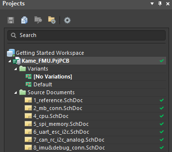
Select the Kame_FMU project then click the Open button at the lower-right corner to open the selected project in the workspace. In Altium Designer, the Projects panel is used to work with and manage projects. After opening the project, it will appear in the panel.
Select File > New > Schematic from the main menus to add the schematic sheet to the project structure.
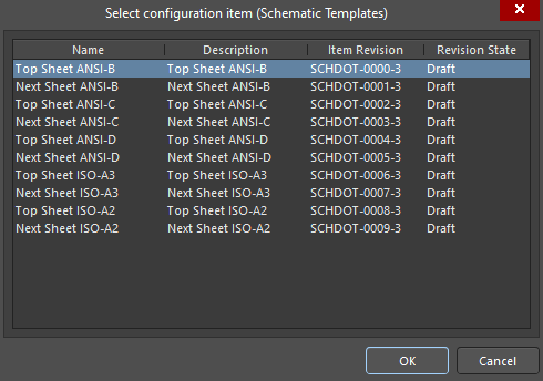
In the Select configuration item dialog, select a sheet template from the listed templates. These templates can be local or cloud-based, depending on your Altium Designer usage strategy. Select Top Sheet ANSI-B then click OK to add a schematic sheet with the selected sheet configuration.
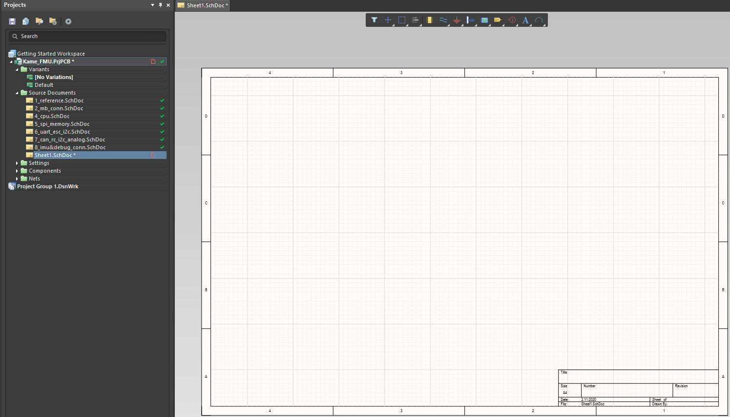
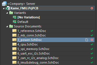
A new sheet with the name Sheet1.SchDoc has appeared in the Projects panel in the Kame_FMU project tree. Also, a ready-to-use schematic document has been opened in the Altium Designer workspace.
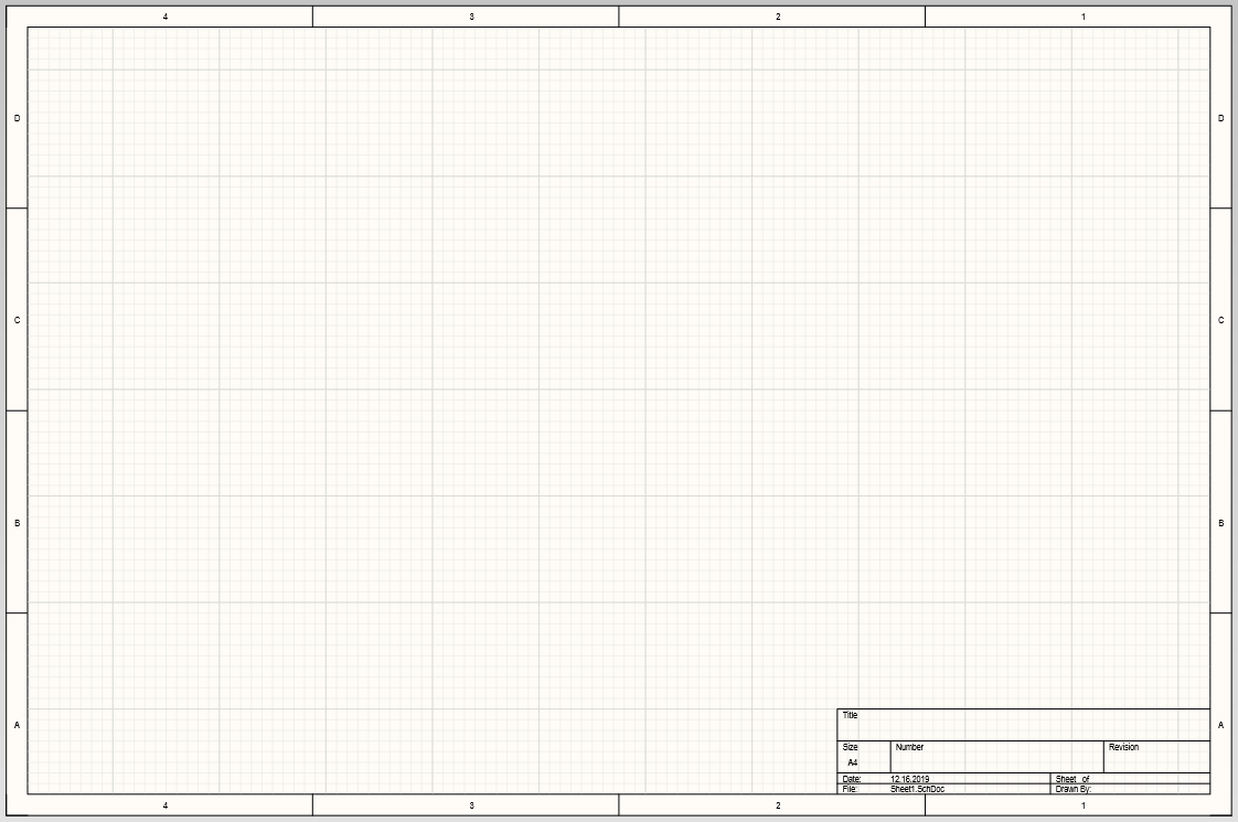
The sheet configuration can be changed at any time in the Properties panel. You can set a Template, Standard or Custom schematic sheet configuration. The template that was set when the schematic sheet was created is active. Let’s change the page size to the default A4 size.
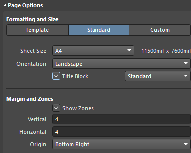
Open the Properties panel if it is not already open. In the Page Options region, select Standard as the Formatting and Size option. In the Sheet Size drop-down, select A4 and enable the Title Block option. In the Margin and Zones region, enable the Show Zones option.
Tip: If the sheet does not have a visible black border, enable it by enabling the Sheet Border option in the General section
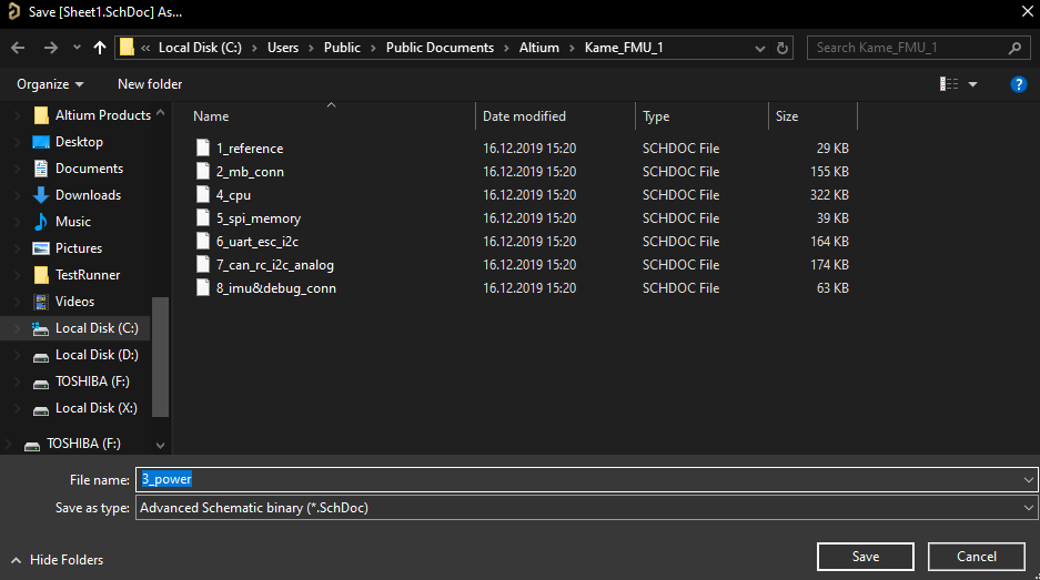
Now we need to save the schematic sheet and give it a name. Select File > Save from the main menus. In the window that opens, specify the file name as 3_power then click the Save button to save the document and rename it in the project tree.
The last step is to make the newly-created schematic sheet available online for the workspace. Since it is part of the project, the project also needs to be saved on the server.
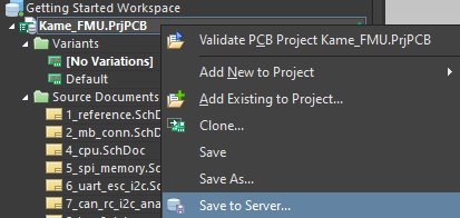
Right-click on the Kame_FMU.PrjPCB project name the select Save to Server to open the Commit to Version Control dialog.
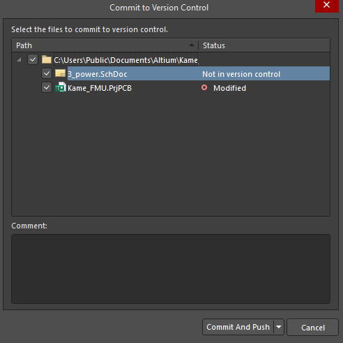
The Commit to Version Control dialog lists all the project files changed during the current session. The schematic sheet added in this chapter is not in the version control on the server so enable the checkbox to the left of the 3_power.SchDoc file. Click Commit And Push to save the enabled files to the server.
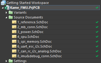
After the file is successfully uploaded to the server, you will see a green checkmark next to all files that make up the project structure. Now the schematic sheet is available online.