Creating PCB Mounting Holes
Our PCB must somehow be assembled into the final drone assembly. This will be achieved by attaching our PCB to the motherboard connector and by special mounting racks, which requires precise positioning of the two mounting holes on the PCB. We can create mounting holes in Altium Designer in two ways.
- Create a mounting hole as a common object using Place > Pad from the main menus. After creating a pad, we need to configure its type (through), the exact size of the hole, the metallization area, and manually assign a net to it.
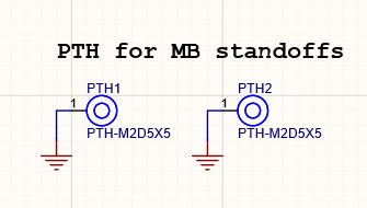
- Create and use a mounting hole as a component that already has the set parameters of the mounting hole. This approach requires that mounting holes are placed on the schematic sheet, as done on 2_mb_conn.SchDoc as shown below. We will use this approach in this guide
Let’s place them.
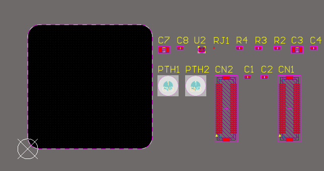
Find the PTH1 and PTH2 holes among the PCB components added during synchronization.
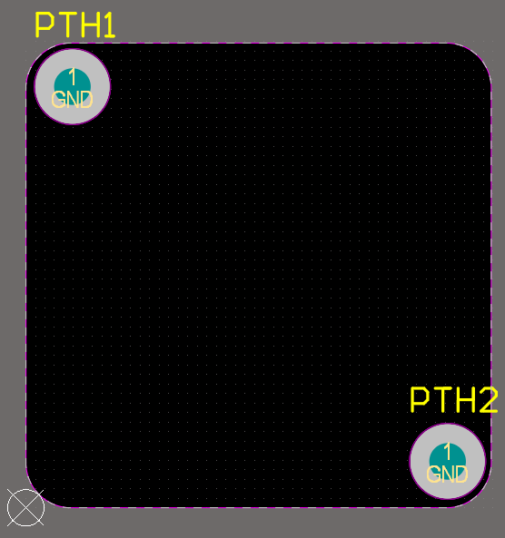
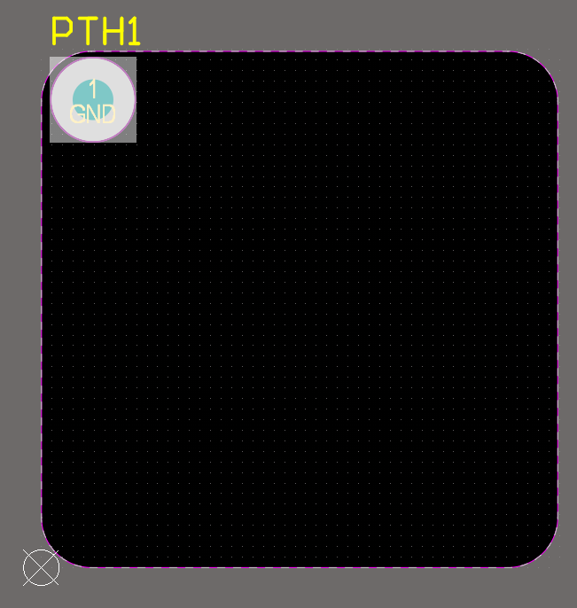
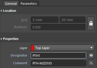
Click PTH1 to select it. We need to place it exactly by X/Y coordinates. In the Location region of the Properties panel, enter 3.1mm as X and 28.1mm as Y. A mounting hole is now located in the upper-left corner of our PCB. To keep it from being accidentally moved, lock the coordinates by clicking the lock icon to the right of the Location region. After locking, the X/Y coordinates in the Properties panel will be grayed out.
Place the PTH2 mounting hole on coordinates (X/Y) 28.1mm/3.1mm then lock it. It should be placed as shown below. The work with mounting holes is complete so now we can move on.