

Assembly Data Outputs
To assemble a designed printed circuit board, it’s required to export (at least) the assembly drawing and pick and place file(s) for automatic component placement. The approach to generating the assembly drawing described in this chapter is intended for quick generation of a draft variant instead of using its high-grade replacement. We strongly recommend using Draftsman for professional, convenient and rapid design of high-quality assembly drawings. It is also necessary to upload the previously created ActiveBOM document. Let’s get started.
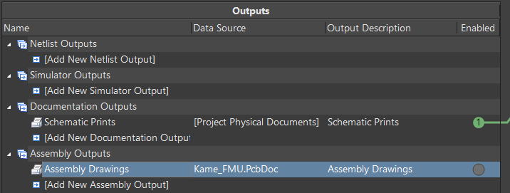
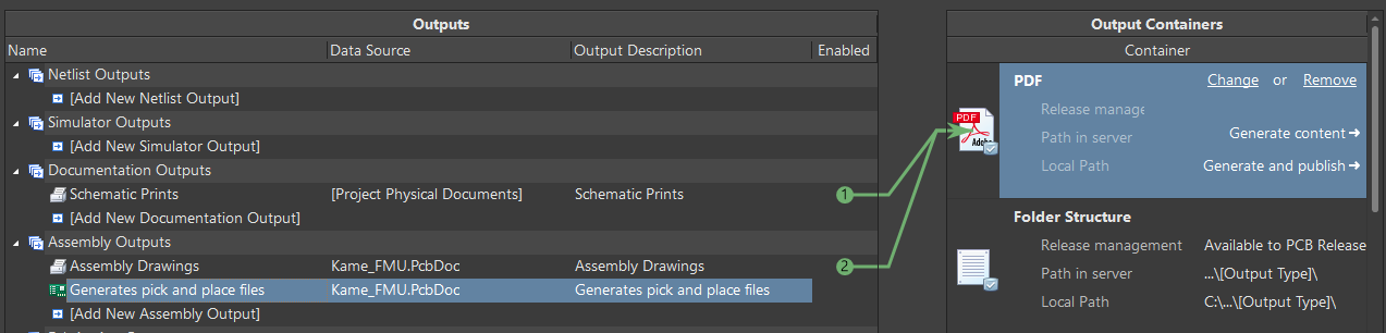
Click on [Add New Assembly Output] in the Assembly Outputs region then select Assembly Drawings > Kame_FMU.PcbDoc to add an assembly drawing to the PCB.
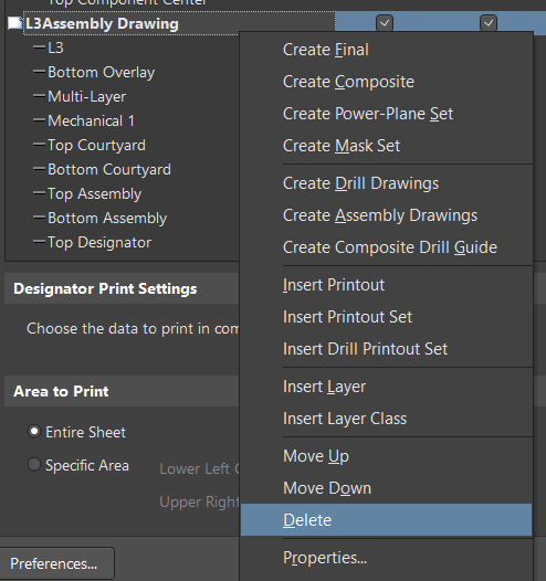
Double-click Assembly Drawings to open the PCB Printout Properties dialog. We need to remove layers that are not required for device assembly (inner layers of the PCB are not needed for the device assembly) and mirror the bottom layer for easier assembly process. In the PCB Printout Properties dialog, right-click on L3Assembly Drawing then select Delete from the context menu then click Yes in the confirmation dialog. Also remove the L4Assembly Drawing layer so that only the TopAssembly Drawing and BottomAssembly Drawing layers remain in the list.
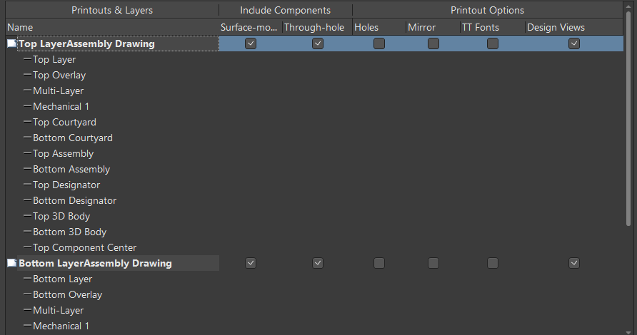
As you can see, the same Overlay, Assembly, Designator, and 3D Body layers are included for the Top and Bottom layers at the same time, which will cause confusion in the assembly drawing, so we need to delete a few layers. While holding Ctrl, select Top Overlay, Courtyard Top, Courtyard Bottom, Assembly Bottom, Designator Bottom, 3D Body Top, 3D Body Bottom, and Component Center Top under Top LayerAssembly Drawing then right-click at one of the selected layers, select Delete and confirm the removal.
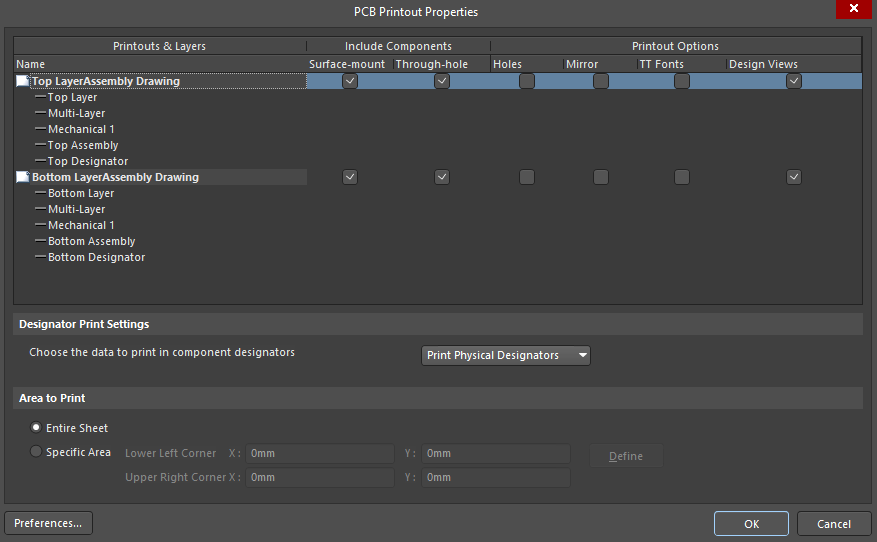
Using the same approach, remove the Bottom Overlay, Courtyard Top, Courtyard Bottom, Assembly Top, Designator Top, 3D Body Top, 3D Body Bottom, and Component Center Top under Bottom LayerAssembly Drawing. The PCB Printout Properties dialog should contain only the layers that are shown in the figure below. Click OK to close the dialog and apply the changes.
Select PDF in the Output Containers region of the OutJob editor then check the Enable circle associated with Assembly Drawings.
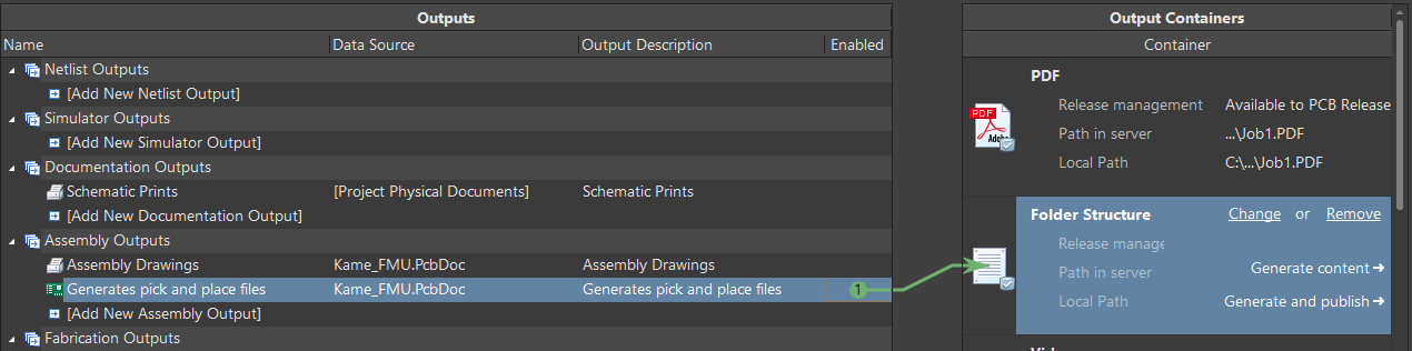
Now we need to add a Pick and Place file. Click on [Add New Assembly Output] in the Assembly Outputs region then select Generates pick and place files > Kame_FMU.PcbDoc.
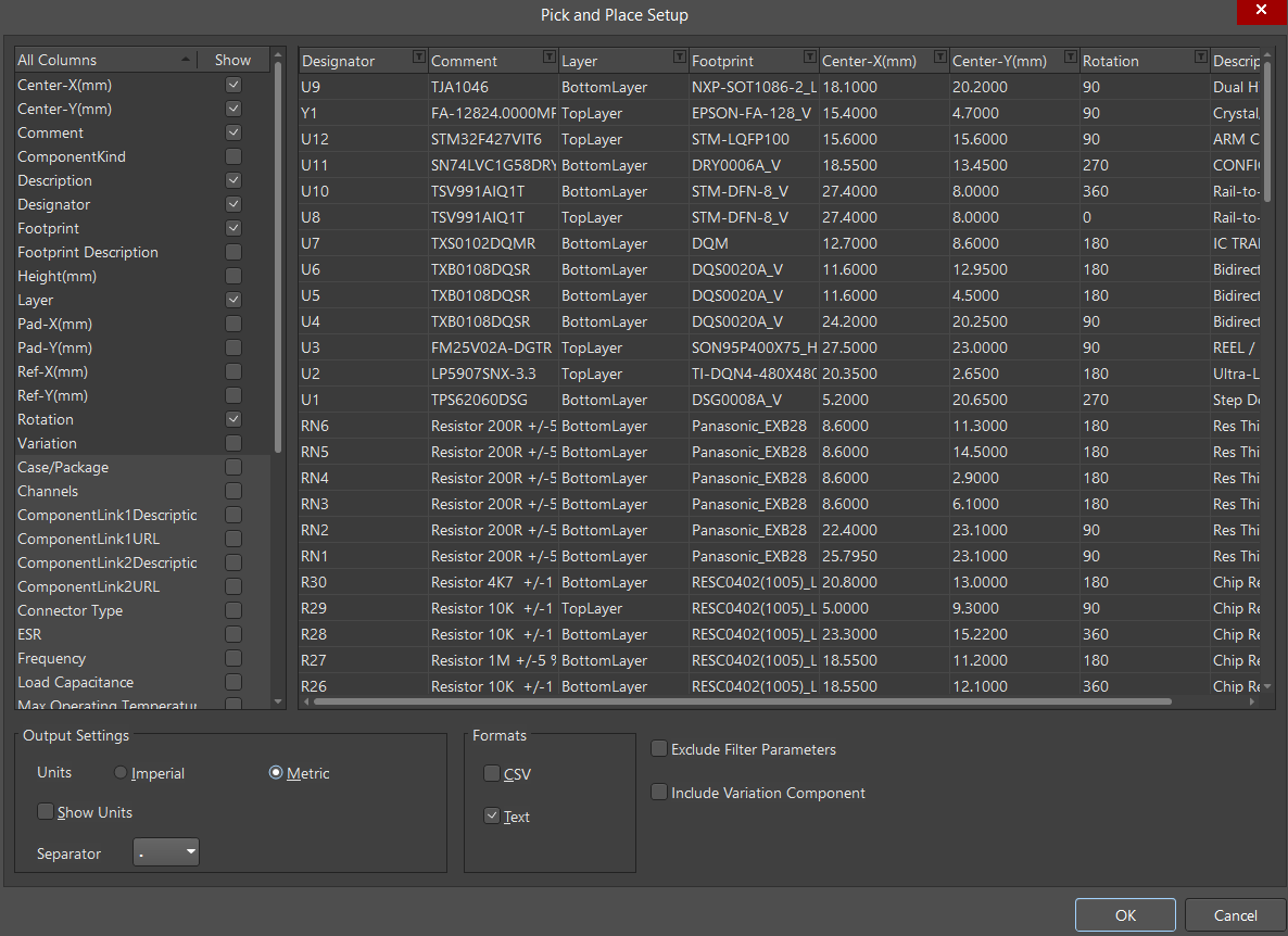
The Pick and Place file is generated in Imperial units by default. Let’s change it to the Metric system. Double-click Generates pick and place files to open the Pick and Place Setup dialog to configure pick and place file properties. In the Output Settings region of the dialog, select Metric. Click OK to save the changes and close the dialog.
Select Folder Structure in the Output Containers region of the OutJob editor. Check the Enable circle for Generates pick and place files.
The last step before exporting all documentation is to add the export of the 3D model of the designed PCB in a universal .step format.
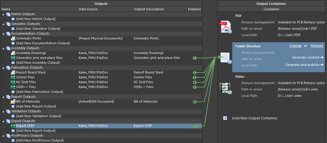
Click [Add New Export Output] in the Export Outputs region then select Export STEP > Kame_FMU.PcbDoc to add a 3D model of the designed PCB as an output file.
Select Folder Structure then check the Enable circle for Export STEP.
All the necessary files are now configured and ready to be uploaded for PCB manufacturing. Select File > Save from the main menus to save the OutJob file. Change the name of the file to Output then save it. This file is now available in the project structure and can be opened, modified and used at any time. Each time you make a change to the PCB construction, you can export all the updated files in just a few clicks.