

Using the ActiveBOM
A BOM (Bill Of Materials) is one of the documents that needs to be obtained during the PCB design process. This document contains a list of all the components with their designators, part numbers, values, and other parameters. Our schematic is ready and we will not make any more changes, so nothing prevents us from creating this document now. To create the document, Altium Designer uses the ActiveBOM editor, which is a powerful tool that brings comprehensive BOM management tools together with Altium Designer's powerful part information aggregation technologies, helping you manage the component selection challenge.
ActiveBOM manages the mapping from the design component (part) to the part that is purchased. For each part used in the project, the linkage between:
- the design component,
- the manufacturer of the part to be fitted to the board,
- and the available suppliers of that part,
is presented as a Solution in the lower region of the ActiveBOM document. Let’s add an ActiveBOM document to our project:
We need to make sure that our drone project is active so that the ActiveBOM document will be attached to the correct project. To activate the project, open one of the project's schematic sheets. The active project is highlighted in the list of projects in gray against the background of its name.
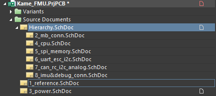
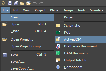
Now we need to add a new ActiveBOM document to the project. To do this, select File > New > ActiveBOM. A new document will appear in the Kame_FMU project tree and a new tab will open with a list of all components.
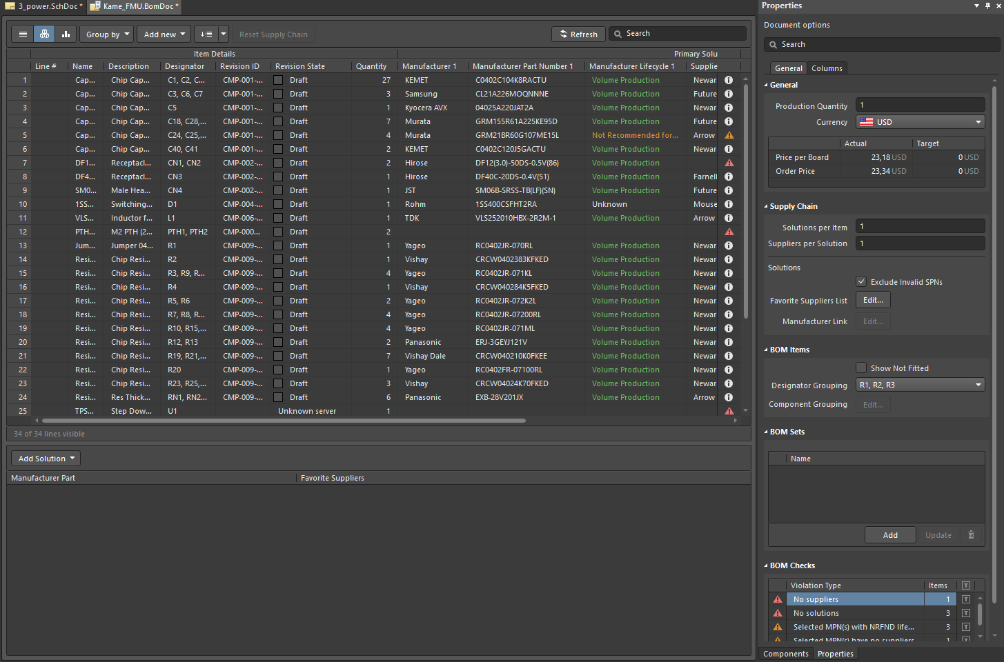
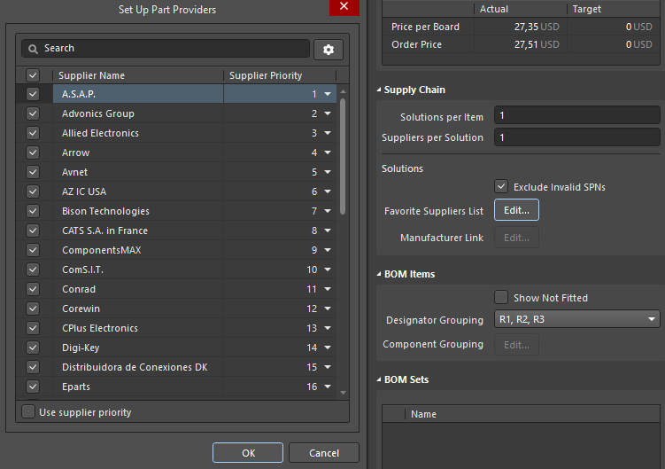
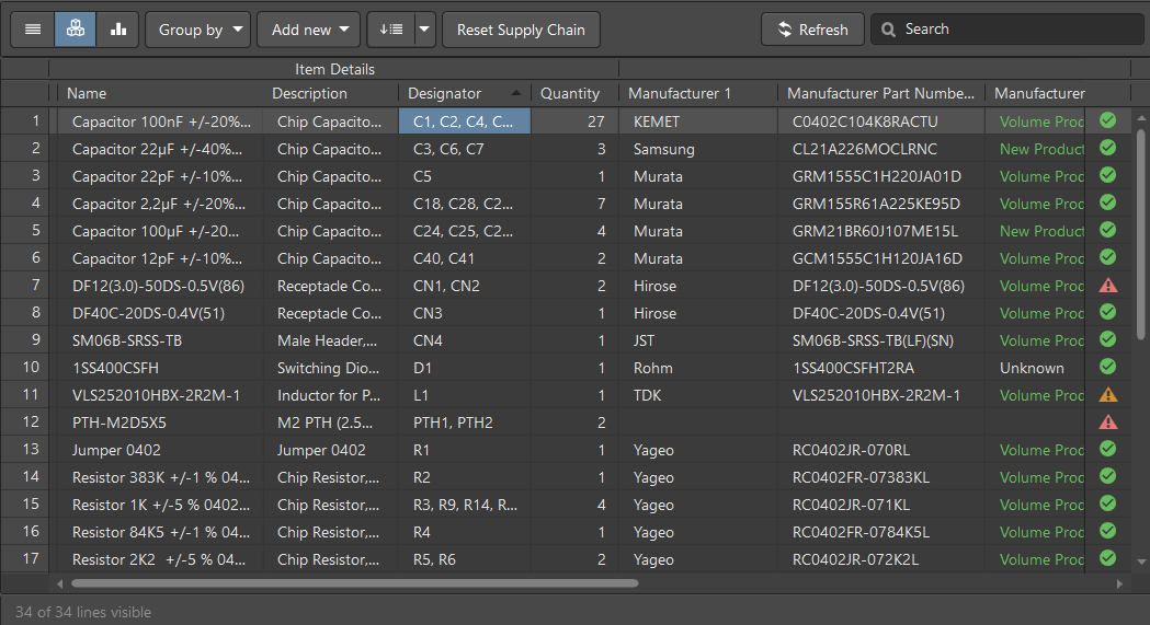
After a few moments, the manufacturer's solution will appear for all components that are placed in the project. Also for each component, you will see the proposed part number, component manufacturer, current component lifecycle stage, unit price, and total price. Powered by Octopart and Ciiva, the ActiveBOM engine automatically compares prices for all presented components from all selected suppliers and chooses the best solution for you. You can select your favorite suppliers in the Supply Chain region of the Properties panel by clicking the Edit button associated with Favorite Suppliers List. In the Set Up Part Providers dialog, you can uncheck suppliers that you don’t need and focus only on providers that are available to you. After making any necessary changes, click OK to save the changes.
Click on a component in the ActiveBOM to display all the component suggestions for that component. When selected, information about the availability and cost of the component is displayed at the bottom of the window allowing you to compare all the possible solutions. Click the desired component/supplier.
Tip: For grouped designators, use the Designator Grouping drop-down in the BOM Items region of the Properties panel to choose the presentation.
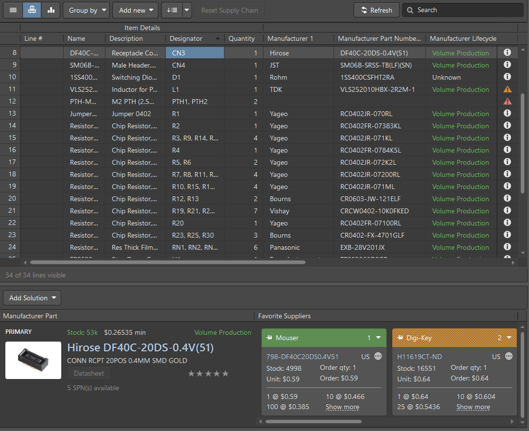
The ActiveBOM includes a set of BOM rules that must be complied with in order to be able to obtain all components without any issues. The rules automatically check each component. The status of each check is displayed as listed below:
 - Clear: There is a solution for the component; all components are available from the supplier.
 - Warning: There is a solution for the component but there are some minor warnings.
 - Error: There is a solution for the component, but there are problems specifically with this component in the design (e.g., an outdated revision of the component in your schematic, NRFND stage, etc.).
 - Fatal Error: There is no solution for this component and this needs to be rectified. Reasons for this error include restricted usage of a component that has an obsolete lifecycle status, component was not found from the suppliers, suppliers data has not been updated for a while, etc.
Tip: You can hover the mouse over the error to view the entire text of the error.
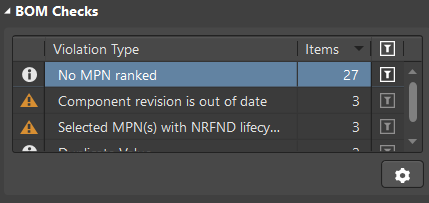
You can see errors and filter them based on their type in the BOM Checks region of the Properties panel. At this stage, we have a lot of warnings with a No MPN Ranked Violation Type because we have not added our rating for the suggested solutions yet. This warning will be fixed later in this section.
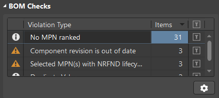
Tip: To sort the BOM Checks region, click on the column heading by which you want the region sorted. To filter the region and show only violations of a certain type(s), click the filter icon of the desired violation.
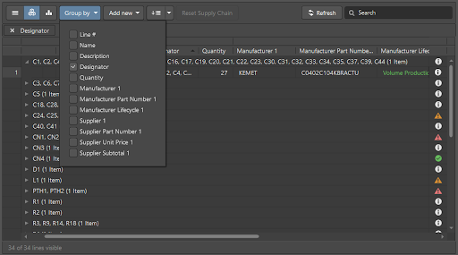
We need to confirm the suggested manufacturer solutions and, if necessary, replace components from our list. To do this, it is easier to sort the list into groups. Let’s group our components, based on their designator, to automatically assign the same solution to all the same components. For our purposes, many capacitors, resistors and resistor assemblies will be combined into groups. To do this, click Group by at the top-left of the BomDoc then enable Designator in the drop-down menu. All components are now grouped and each line is a list of components with the same part number.
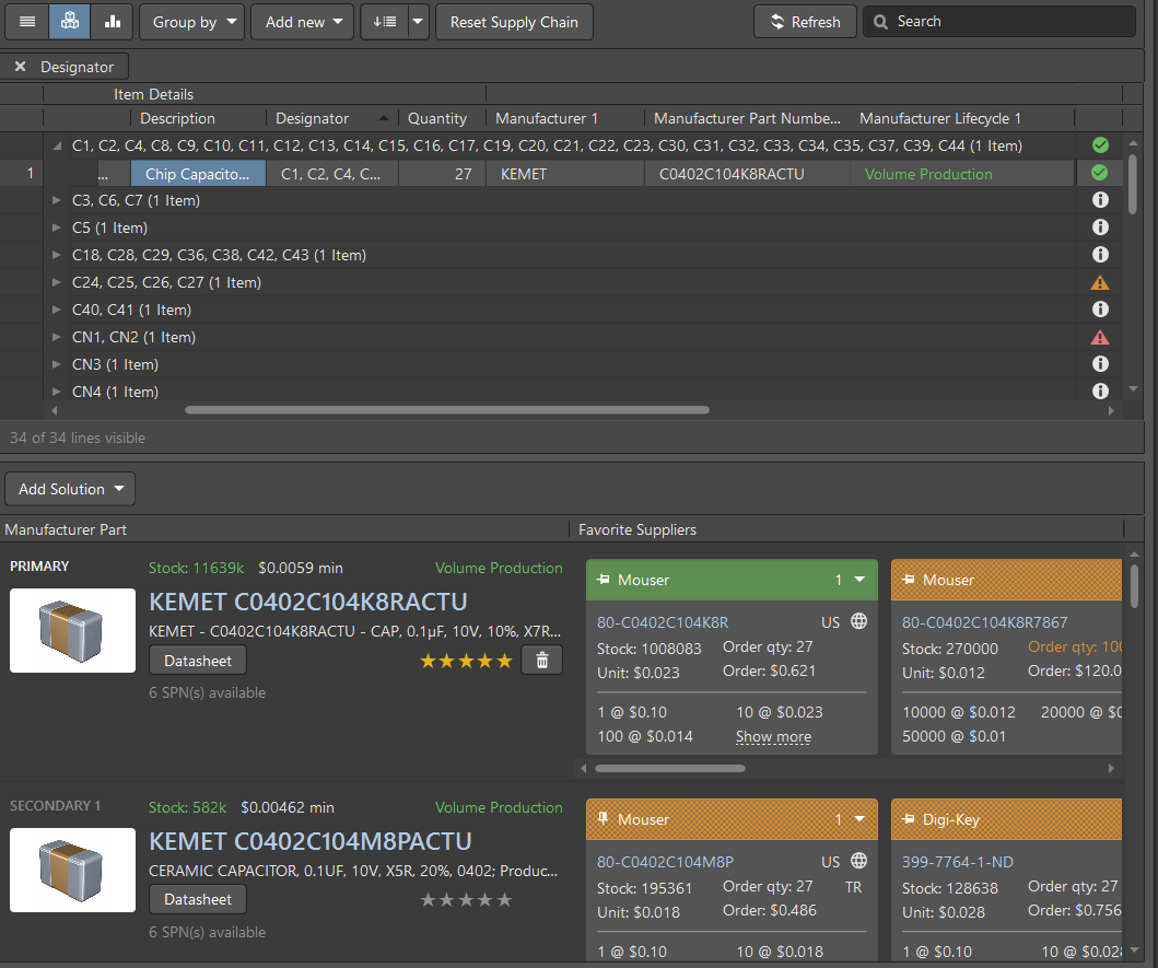
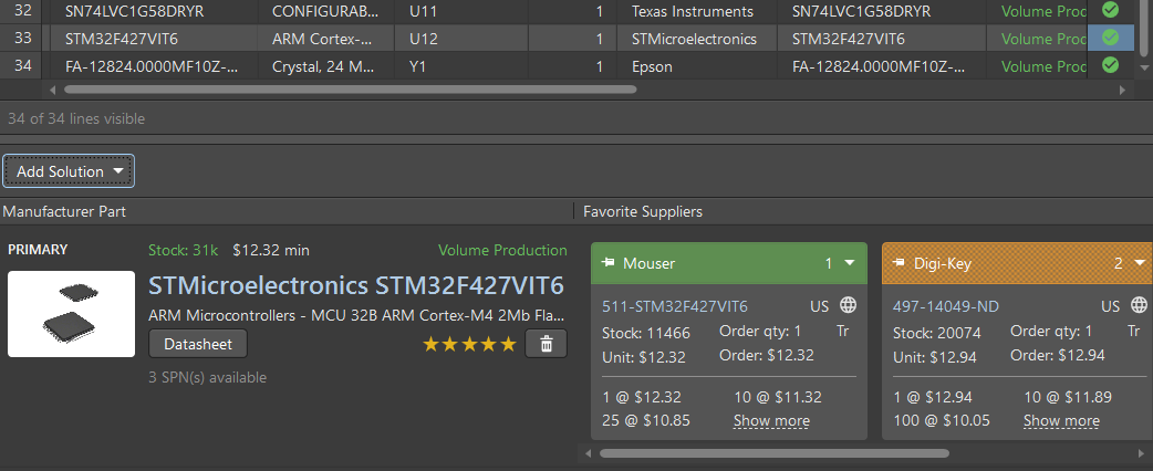
Let’s take a look at the largest group of capacitors. Expand this section then click on a line in an expanded section to see the suggested part solution. We can see a warning that we have no MPN ranking. The default state for a new BOM Item is that the suppliers are ranked automatically. You can set your personal preferences when selecting components using a five-star rating scale. The ActiveBOM engine will list components with the highest rating. Let’s define the rank of this group. Take a look at the Manufacturer Part region. You may notice that each component of each supplier's name is highlighted in a color. Green indicates the optimal solution in terms of price, availability of the supplier, lifecycle stage, and other parameters. Orange denotes an acceptable part and supplier solution, although it may be more expensive or only small quantities are at the supplier's disposal. Red indicates that this is a risky solution; components could be at the end of the lifecycle or insufficient quantities are in stock. Also, the current component lifecycle stage is displayed in the available solution list. Choose a solution highlighted in green; rate it five stars by clicking on the rightmost star. The warning for this group will disappear and the status turns green.
Tip: If desired, you can change the rank or remove it by clicking the trash can icon associated with the rating.
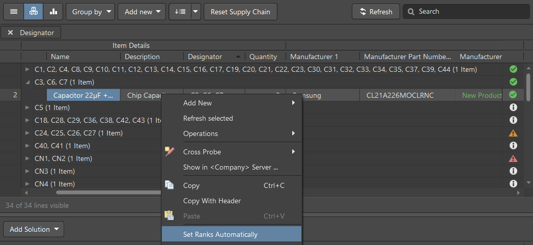
You can automatically assign a five-star rating to the most appropriate component by the ActiveBOM version. Expand the next group with capacitors then right-click on the Name and select Set Ranks Automatically. The maximum rating for the most suitable and profitable component is now set automatically.
Now let’s set the ranks automatically for all the remaining components with this warning. Remove the designator grouping by clicking Group by at the top-left of the BomDoc then disable the Designator checkbox. Click the filter icon associated with the No MPN ranked violation in the BOM Checks region of the Properties panel to show only components with this warning.
Hold the Shift button then select all components in the BOM list, right-click on one of the selected parts then select Set Ranks Automatically from the context menu. The warning is now fixed for all components.
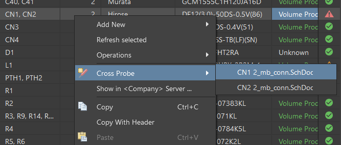
There is a fatal error with components CN1 and CN2. Hover the mouse over the error icon to see that the component revision is out-of-date and restricted for usage. Therefore, we need to update this component on the schematic to the latest revision. We can quickly locate this component by right-clicking on it then choosing Cross Probe. We also need to select the schematic sheet(s) on which this component is placed. In our case, two components are placed on the same sheet. After selection, the schematic sheet will open and you will see the violating component.
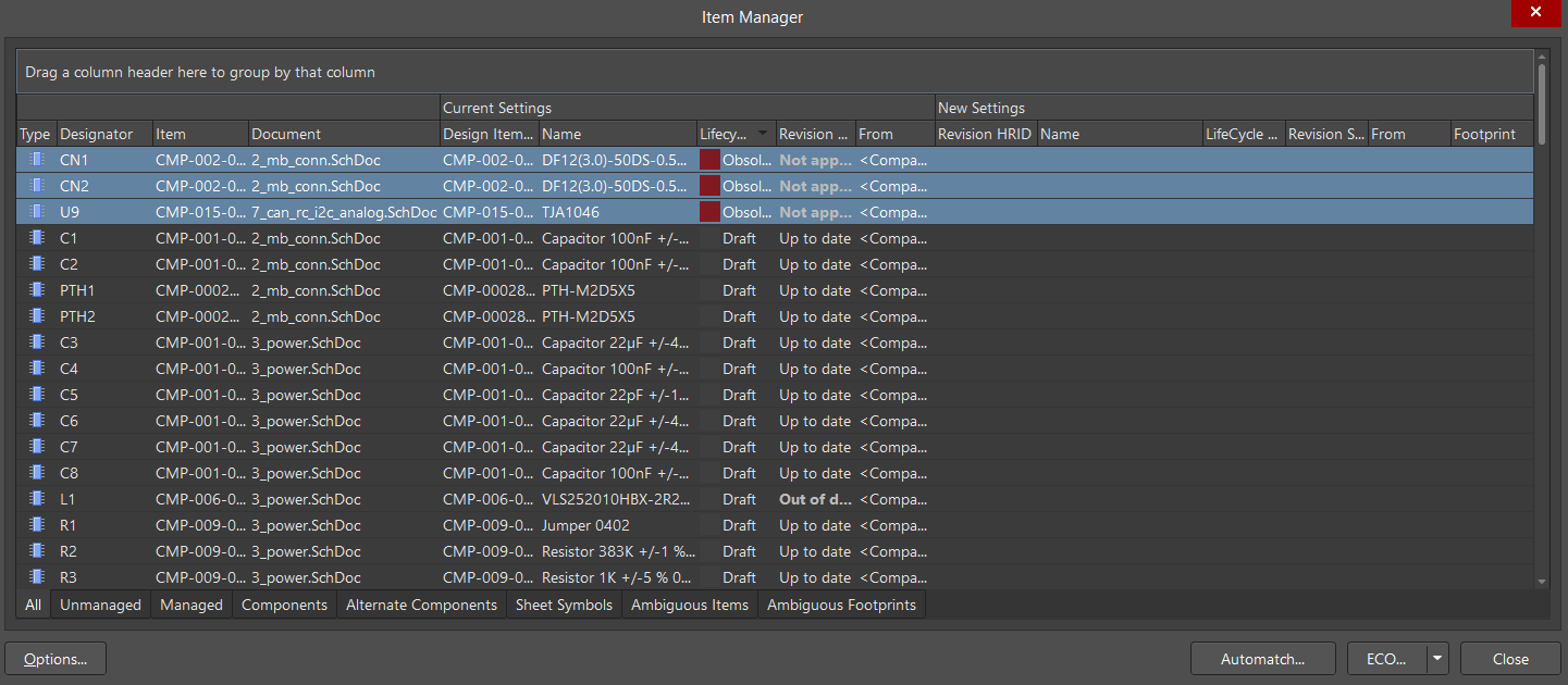
You can update only the selected component by selecting Tools > Update Selected From Libraries, however, we strongly recommend that you update all components by using the Item Manager dialog (Tools > Item Manager). Click the Lifecycle State column header to sort the list by that column. Components with Obsolete status should be at the top of the list. As you can see, there is an additional component in the Obsolete lifecycle state. This is the reason for updating all components rather than only the selected component.
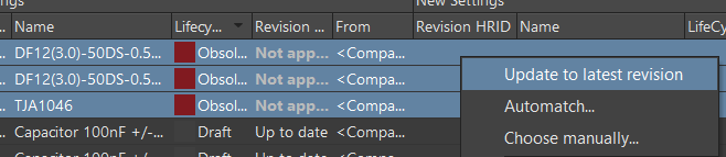
Select all Obsolete components. Right-click on one then select Update to latest revision.
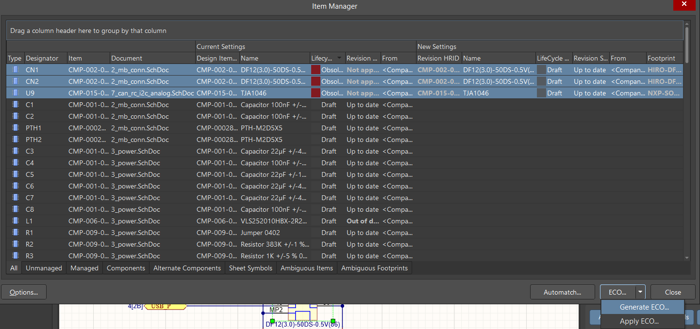
The New Settings region on the right side of the dialog is now completed for the selected components. We need to apply the new settings by generating an Engineering Change Order (ECO). Click the ECO button at the bottom of the dialog then select Generate ECO. In the Engineering Change Order dialog that opens, validate and execute the changes and be sure to set new parameters.
Open the BomDoc. Click Refresh to update the part solutions.
Find the U12 component. Hover the mouse over the error icon; this component has No solutions. Let’s add a solution manually.
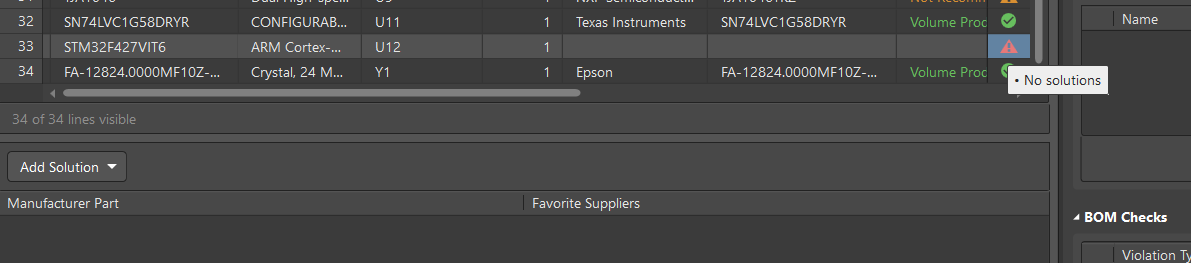
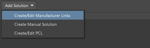
To do this, click the Add Solution button above the Manufacturer Part region then select Create/Edit Manufacturer Links. The Edit Manufacturer Links dialog opens.
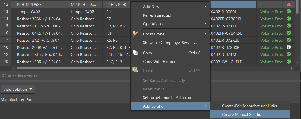
Tip: You also can open the Create Manual Solution dialog by right-clicking on a component in the BOM grid then selecting Add Solution > Create Manual Solution.
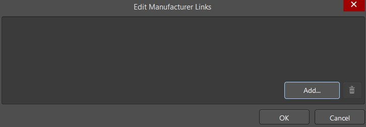
Click the Add button to select the component. The Add Part Choices dialog opens in which you can select the desired part solution. This dialog is similar to the Manufacturer Part Search panel that can be used during schematic component placement. Part Number STM32F427VIT6 of the U12 component has been entered automatically as a search request and there is an available solution. Select the available solution then press OK to apply the changes.
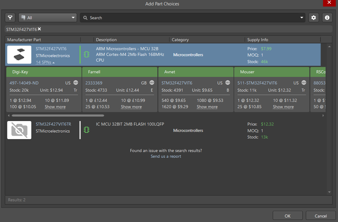
Tip: Click on nn SPNs in the selected solution to see its availability, price, etc.
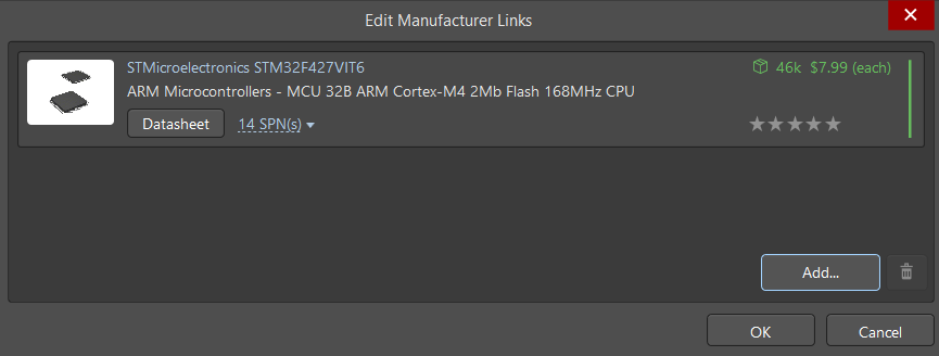
After selecting the solution then closing the Add Part Choices dialog, you’ll see that the selected solution is now displayed in the Edit Manufacturer Links dialog. Press OK to proceed with the selection. The selected part choice is now defined for U12 as shown by its state. Don’t forget to rate the solution!
We also have two mounting holes that are defined as components in our BOM. These mounting holes will be fitted with fixing racks to the other PCBs of our drone so we need to include the racks in our BOM by creating a manual solution. Select PTH1, PTH2 in the BOM grid, right-click then select Add Solution > Create Manual Solution.
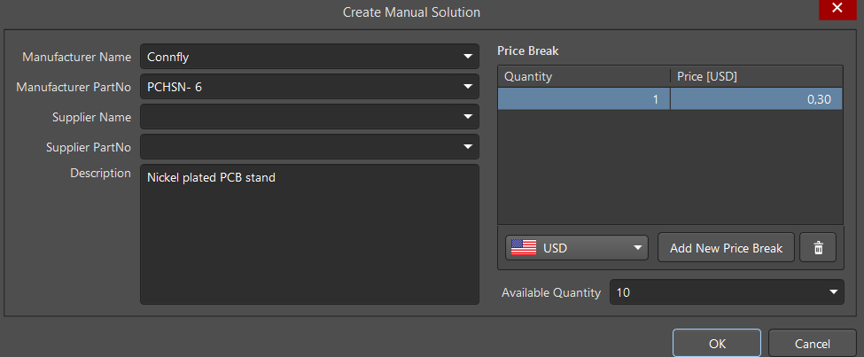
In the Create Manual Solution dialog that opens, specify the solution parameters by entering them as shown below then click OK to save the solution settings.
That's it - our document is ready and Altium Designer is up-to-date using modern, accurate, and convenient process. It will be generated to a separate file (for example, .xlsx) using an OutJob, which is described in a separate chapter.