Creating Component Symbols
We sincerely hope that this guide has inspired you to create your own project. However, in order to design your projects, you will need a set of created components that form the functionality of your device. Earlier in this guide, you used the provided cloud library in which all the necessary components had already been added. Although the integration of Octopart with Altium Designer includes a large coverage of the component base, they cannot absolutely cover all the components in the world and there is a possibility that nobody has yet created the component that you require. Therefore, you need to be able to create components for the library manually. As already described in the first chapters of this guide, each component of the library consists of a symbol, a footprint, models, and a set of additional parameters. This chapter will introduce to you the main approaches to creating the component symbols. It also describes the approach to creating managed components with their own lifecycles, version control, and many other benefits. The approach to creating local libraries has a similar process. As an example, let’s create components GSB343K33HR and MBT3904DW1T1G.
Symbol Creation Using the Symbol Wizard
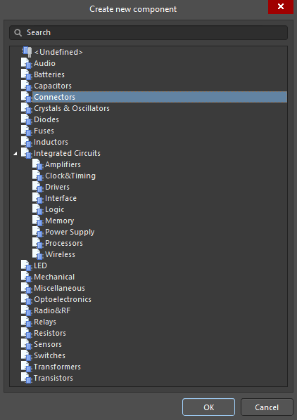
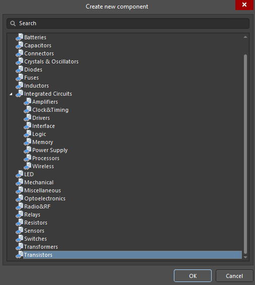
Connect to the required workspace then select File > New > Component from the main menus. The Create new component dialog that opens allows you to specify the type of the component to create. The first component will be the USB3.0 GSB343K33HR connector, so select Connectors in the list then click OK.
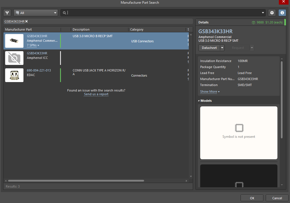
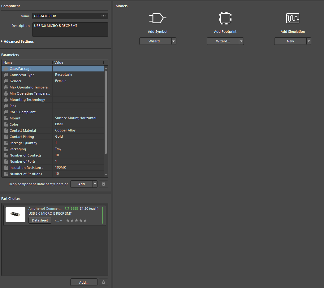
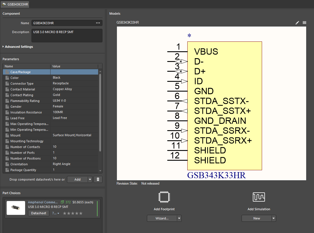
The editor that opens is the starting point for component creation. This editor specifies the name of the future component, its description, parameters, symbol and footprint, datasheet, and possible part choices. First of all, let's specify the name, description and set of parameters for our component. This can be set very quickly using the Manufacturer Part Search panel. Open the panel by clicking the ••• symbol in the Name field to define the component name and parameters. In the Search field, enter GSB343K33HR, which is the part number of the required component then press Enter. Select the GSB343K33HR component then click OK.
 icon, the symbol and footprint will be automatically imported after clicking OK.
The component symbol can be created either manually or by using the Symbol Wizard, which allows you to quickly create component symbols. In most cases, it is recommended to use the Symbol Wizard to create basic symbols. Creating characters manually gives you more flexibility, but it takes more time and attention. This component will be created using the Symbol Wizard. Click the Wizard button below the Add Symbol icon in the Models region to open the Symbol Wizard dialog and begin creating a new symbol.
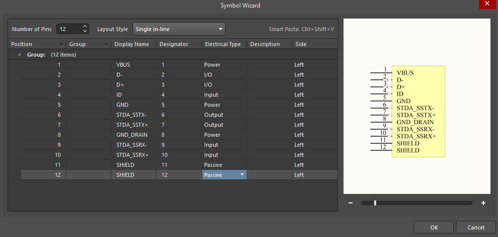
The GSB343K33HR component is a 12-pin connector. For convenience, in the schematic design, all the pins of components of the "Connector" type are usually placed on one side and this component is no exception. In the Symbol Wizard, in the Number of Pins field, enter 12 (or use the arrows to select). Use the Layout Style drop-down to select Single in-line. The grid is intended for assigning a name, group, designator, electrical type, description, and side for each pin. The Display Name is assigned by double-clicking in the column then entering the desired name. Electrical Type is selected using the drop-down menu. The preview displayed on the right side of the dialog shows the current symbol view. Define the pin parameters as shown in the figure below. After adding and configuring all the pins, click OK to save the symbol and assign it to a created component.
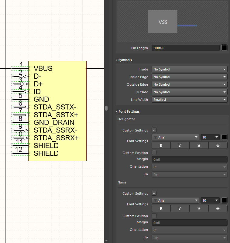
After clicking OK, a new tab opens in the main design space where the generated symbol is displayed. This tab allows you to fully customize its appearance. Let's change the pin length and font to make this symbol visually correspond to other symbols in the library. Using right-to-left selection, select all pins. In the Properties panel, change the Pin Length value to 200 mil. Expand the Font Settings region of the panel. Check the Custom Settings boxes for Designator and Name to unlock editing for font settings. Use the Font Settings drop-down to define Arial as the font.
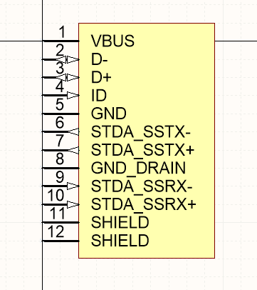
You may notice that there is a crosshair of black lines in the center of the symbol editor. Its purpose is to specify the point to which the symbol will be attached when it is placed from the Components panel. It is recommended to place the end of the first output of the component at this crosshair. Select the entire symbol and place it as shown in the figure below.
Save the symbol by clicking Shift+S then close the tab. The updated symbol now appears in the component editor.
 icon in the upper right corner of the editor.
Manual Symbol Creation
The next logical step to complete the component is to add a footprint and upload the finished component to the server. This will be done in the next chapter. Do not close the tab with the GSB343K33HR component since we will return to it in the next chapter. Let's create another component using a multi-part feature. As an example, let's create transistor pack MBT3904DW1T1G consisting of two transistors in one 6-TSSOP package.
Select File > New > Component from the main menus. In the dialog that opens, select Transistors as the type then click OK.
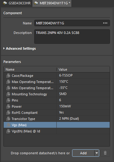
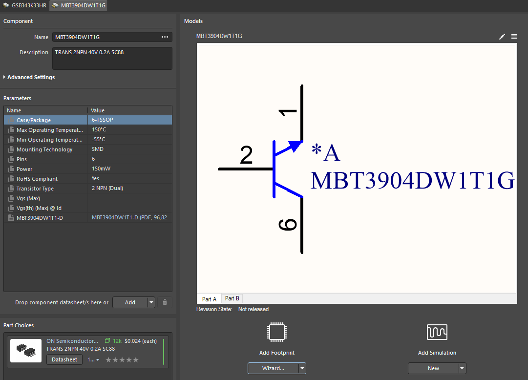
Enter MBT3904DW1T1G as the Name. Do not choose any of the suggested options after entering the name as we will create this component manually. Enter TRANS 2NPN 40V 0.2A SC88 in the Description field. Define the following values in the parameters section:
Case/Package: 6-TSSOP
Max Operating Temperature: 150
Min Operating Temperature: -55
Mounting Technology: SMD
Pins: 6
Power: 150 mW
RoHS Compliant: Yes
Transistor Type: 2 NPN (Dual)
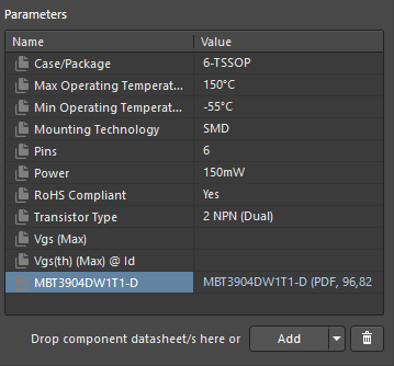
Let's add the datasheet to our component so that we can access it at any time. Download this file and store it in a convenient location. Click the arrow to the right of the Add button then select Datasheet. Select the downloaded PDF file then click Open to attach it to the component.
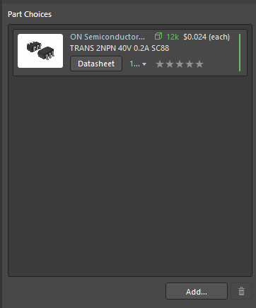
Let’s add a defined part choice for this component. Click the Add button in the Part Choices region to open the Add Part Choices dialog. Select the first component in the search results then click OK. In the Use component data dialog, select the Use only name option since the name and parameters are already defined for this component. A new part choice now appears in the Part Choices region.
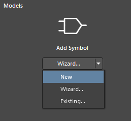
Click the arrow to the right of the Wizard button below Add Symbol then select New to create a new symbol.
When a component has different functional groups or repeating identical parts (e.g., resistor and transistor packs), it is more convenient to implement it with a multi-part component. In this case, the component MBT3904DW1T1G consists of two NPN transistors, which are more convenient to present in the form of such a symbol. Let's add the second functional part of the symbol.
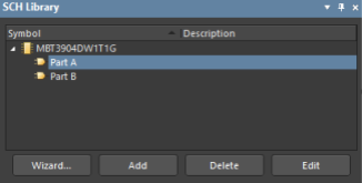
Open the SCH Library panel in the symbol editor. Click the Add button at the bottom of the panel to add a new part to the symbol. Click Part A to make this part active.
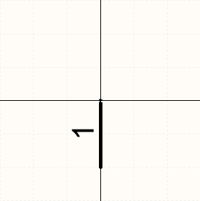
Select Place > Pin from the main menus to start pin placement. Press the Tab key to edit the properties of the symbol being placed. In the Properties panel, define the Designator as 1 and Name as E. Click the visibility icon to the right of the Name field to hide the name. In the Electrical Type drop-down, select Passive. Enter the Pin Length as 200 mil . Define the font as Arial for the Designator. Place the edited pin as shown in the figure below using the Spacebar for rotation.
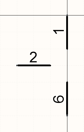
Place two more pins as shown in the figure below. Name pin number 2 B and pin number 6 C.
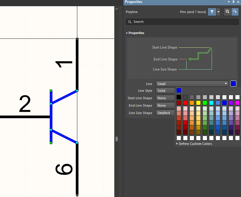
The graphic part of the symbol can be formed by the placement of any graphical primitives, such as lines, rectangles, arcs, and polygons. Using Place > Line from the main menus, draw three lines as shown in the figure below. To place the lines at an angle, use the Spacebar to change the drawing mode.
After placement, select all drawn lines then define their color as blue using the Properties panel. Right-click to finish line placement.
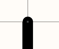
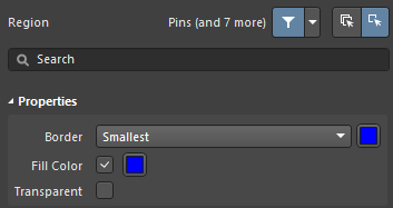
Now we will add the last detail - an arrow indicating the type of transistor. In this case, it is an NPN transistor, so the arrow must be placed in the direction of the emitter, which is represented by pin 1. Select Place > Polygon from the main menus. Press Tab then define the parameters in the Properties panel as shown in the figure below.
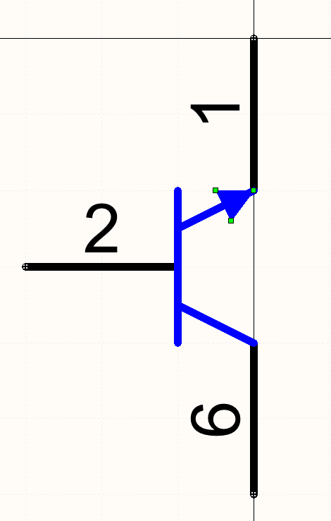
Activate the 10 mil grid and draw an arrow as shown in the figure below.
The first part of the symbol is finished and now we need to finish Part B to make the symbol complete. Select all primitives in Part A and copy them. Select Part B in the SCH Library panel and place the copied primitives. To complete the symbol, perform the following for Part B:
- Change Pin 1 designator to Pin 4
- Change Pin 2 designator to Pin 5
- Change Pin 6 designator to Pin 3
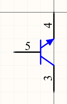
Part B of the symbol should now look like the figure below.
Make sure that the number of pins on all parts of the symbol corresponds to the number of pins of the component. Save the symbol in the symbol editor by pressing Shift+S then close the tab. After saving, the updated symbol appears in the component editor. Do not close the component tabs since we will be using those tabs in other chapters to add footprints and to release the component to the server.


