Component and Library Management
/ Work with Component Templates
Completed
Sign In To Save Your Progress
Click if you find this content useful
Next Article –
Component and Library Management
Work with Component Templates
In order to streamline component creation, component templates are used to predefine settings for reusable components in the workspace. They function similarly to a recipe in providing specifications which will later auto fill for future components. Component templates allow users to predefine:
Component parameters
Default values
Required fields
Naming schemes (IDs)
Storage folders
Linked models
Component types
Users can then create generic components as placeholders in a schematic until a final component is determined.
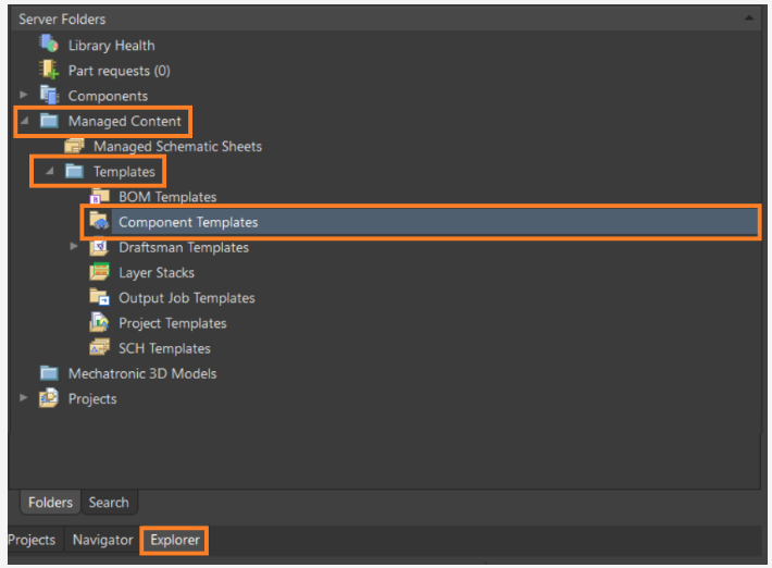
To create a component template, begin by navigating to the Panels > Explorer panel on the bottom right of the screen.
Fig. 1 - Open the Explorer Panel
In the Explorer Panel, navigate to the Managed Content > Templates > Component Templates folder.
Fig. 2 - Open the Component Templates Folder
In the Revision ID Menu on the Explorer Panel, find a component template of choice (i.e. capacitor for this example), right click on it and select Operations > Make a Copy to clone the template.
Fig. 3 - Make a Copy of a Template
In the Parameters menu of the new Capacitors Template under Default Value, update the model file, if desired. This can be done by right clicking in the ... in this field.
Fig. 4 - Add a model, if desired
Next, right click on the Copy of Capacitors Tab at the top and click on Close Copy of Capacitors*.
Fig. 5 - Close the Template
Select Save in the menu that opens.
Fig. 6 - Save the Template
Creating a Generic Component
Now that a component template has been created, the next step is to create a generic component. Generic components are intended to be placeholders that can be easily replaced with a suitable component later in the design process. They also can be considered virtual or parametric components which are added to a particular template as a default model.
For example, if we want to add a battery to the circuit without specifying the exact component, we can perform the following steps:
In Altium Designer, in the Explorer panel, browse to the Component Templates folder where the required Batteries template resides (Managed Content » Templates » Component Templates for the default Workspace activation/installation, as shown in the image below).
Fig. 7 - Explorer panel and component templates
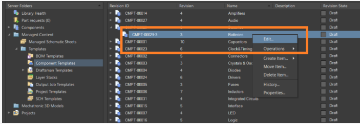
Open the Batteries component template. Click on Edit.
Fig. 8 - Edit component template
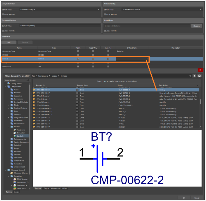
Add a suitable default symbol model parameter reference (Components >> Models >> Symbols) to the SCHLIB. The specified symbol model could be an existing symbol that has been cloned and edited from another symbol or a custom symbol that has been created from scratch.
Fig. 9 - Selecting a symbol
Save the edited template to the Workspace (File » Save to Server). The presence of a symbol model in the updated template causes a Batteries generic component tile to be added to those available in the Components panel.
Placing a Generic Component
Tip: To see a new generic component in the Components panel after it is created, Altium Designer may need to be restarted.
Open the Components panel.
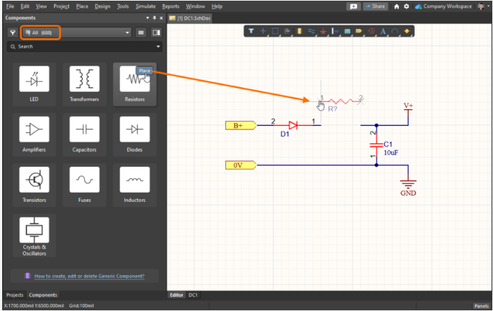
Click on the button within a generic component tile to attach the component to the cursor for placement in the active schematic document. Selecting the tile itself will open that component type category in the panel.
Fig. 10 - Placing a generic component from the Components panel
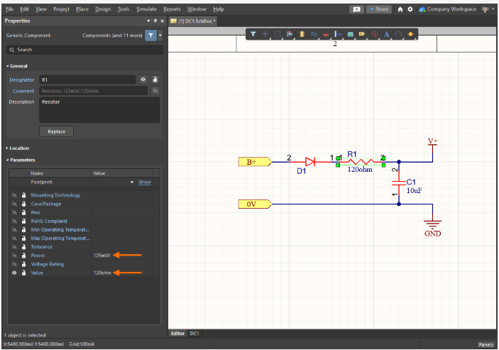
Select a placed generic component to access its properties in the Properties panel. The related component template determines the available parameters (Resistors in the example shown here). Parameter values can be manually entered or selected from a drop-down menu.
Fig. 11 - Specifying the parameters of a generic component
Replacing a Generic Component
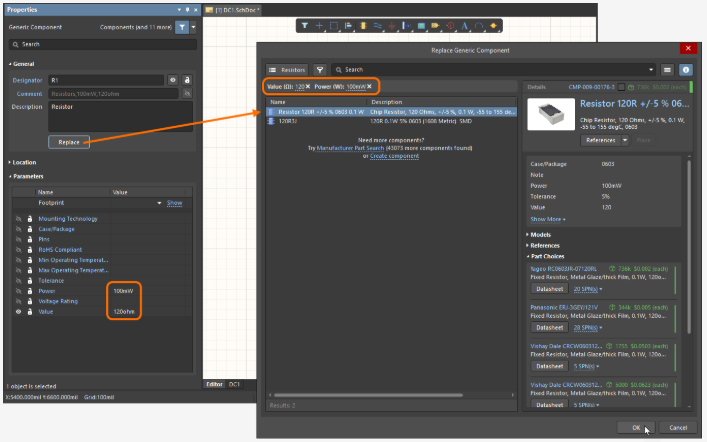
When it is time to replace the generic component with a specific physical component, click the Replace button in the Properties panel. This can also be done from Tools >> Item Manager or the project's ActiveBOM document.
Fig. 12 - Replacing a generic component with a manufacturer's part
Parameter values applied to the generic component are automatically used as search terms in the Replace Generic Component dialog box. This dialog allows you to choose a suitable replacement component from the filtered results. 🎬How to Place a Generic Component.