


Preparing Fabrication Data
Gerber X2 is a direct, and much advanced, evolution of the Gerber RS-274X standard and adds a large range of additional data for PCB fabrication and assembly. Compared to the RS-274X standard, the Gerber X2 format includes critical information, such as layer stack definitions and pad and via attributes. A prime advantage of the Gerber X2 format is backward compatibility with the old Gerber RS-274X standard. Being a multi-file standard, a target fab/assembly house that has not moved to the new standard can extract the traditional Gerber file elements as needed. This may be a significant advantage for those unwilling to tackle a major shift in fabrication file formats, or for fabrication houses with inflexible equipment and software.
The overall benefit of adopting the Gerber X2 format for transferring board design data to fabrication and assembly houses is the rich set of manufacturing data included in the file set and the backward compatibility to the previous standard for a low-risk upgrade path. With a full implementation at both ends of the CAD-CAM chain, the risks associated with data misinterpretation, file errors and variable data interpretation can be largely eliminated
With a project PCB file as the active document, the Gerber file set can be generated by selecting File » Fabrication Outputs » Gerber Files or File » Fabrication Outputs » Gerber X2 Files from the main menus. This opens an appropriate Gerber Setup or Gerber X2 Setup dialog in which you can define the plot layers and general configuration applied during the export process. See the collapsible sections below for detailed information on options and controls provided by these dialogs.
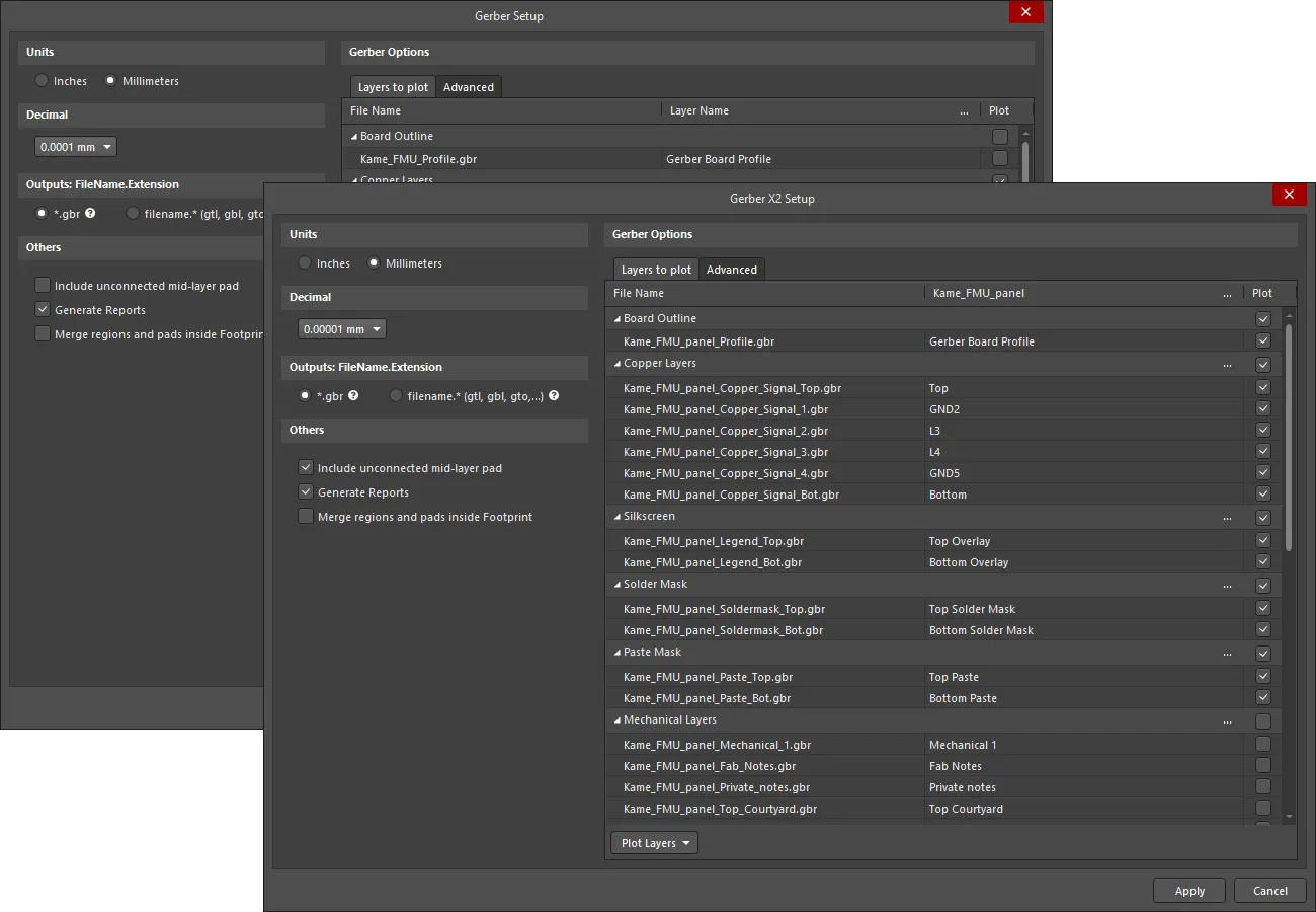
Gerber Setup and Gerber X2 Setup dialogs
Output is generated in the location defined in the Output Path field on the Options tab of the Project Options dialog. Generated file names will include the name of the PCB document.
The generated Gerber output is also opened as a composite CAM document that can be edited and/or saved into the current project and managed via the CAMtastic panel.
