News & Updates


Blog
•
How to Use a Multicad Viewer for Seamless Collaboration
Because ECAD formats are typically incompatible, teams often struggle with versioning, conversions, and fragmented review processes. This article breaks down how multi-CAD viewers provide a unified, read-only environment that supports structured design reviews, comments, and task assignment across disciplines.


Blog
•
Best Online ECAD File Viewers for Engineers and PCB Designers
Sharing PCB designs doesn’t have to be complicated. Check out the best online ECAD viewers that let anyone view and collaborate on designs right from a browser.


Blog
•
Rigid-Flex PCBs in Consumer Electronics
Rigid-flex PCBs help modern devices get smaller, lighter, and more compact by eliminating connectors and fitting into tight 3D spaces. This article explains how to design them properly to avoid common reliability issues.

Blog
•
From Design to First Assembly: Complete Your BOM & Plan Your Build
This webinar walks through the complete post-release workflow, from generating a managed BOM to sourcing components and assembling the first prototype. It demonstrates how integrated tools streamline data enrichment, supplier selection, and guided assembly to reduce delays and errors.

Blog
•
The Future of BOM Management: Trends and Innovations
BOM management is no longer just a checklist. It’s becoming a real-time engine for smarter decisions! Discover how AI, automation, and connected systems are transforming BOMs into powerful tools for navigating supply chain uncertainty.


Blog
•
How to Use a Multicad Viewer for Seamless Collaboration
Working across different ECAD tools can make design reviews messy and inefficient. This article shows how a multi-CAD viewer simplifies collaboration by letting teams view, comment, and manage designs in one place.
NEW

Blog
•
Breaking the Multiboard Bottleneck: How Unified Design Solves ECAD–MCAD Disconnects
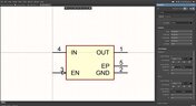
This article examines how fragmented ECAD-MCAD workflows create costly misalignments, late-stage conflicts, and inefficiencies in multiboard system design. It shows how unified, collaborative platforms enable real-time synchronization, digital twins, and cross-domain visibility to eliminate rework and streamline development.

Blog
•
Altium Designer vs. Flux For Professional PCB Projects
Choosing the right PCB tool can define your entire design workflow. Discover how Altium Designer empowers professional product development, while Flux.ai keeps things simple for fast experimentation.

Blog
•
Rigid-Flex Stackups: Where Good Designs Go Wrong Before Layout Even Starts
Rigid-flex stackups are more complex than they seem and getting them wrong early can lead to costly failures later. This article shows how smart decisions around materials, transitions, and layer structure help ensure a reliable design.


Blog
•
From Complexity to Clarity: Smart Design Reviews for Agile Engineering Teams
Understand how structured design reviews within Altium Agile Teams enhance visibility, traceability, and cross-team collaboration. This webinar highlights methods to detect issues early and optimize your development workflow.

Blog
•
Building a Local-LLM Datasheet Extractor for IC Driver Development
Parsing long datasheets manually slows down embedded development and introduces errors. This article shows how to use a local LLM pipeline to convert datasheets into structured data that speeds up driver creation.

Blog
•
Types of Simulation Tools For PCBs
PCB simulation isn’t one-size-fits-all and that’s where it gets interesting! Discover the wide range of tools available, from quick circuit checks to advanced multiphysics simulations, and how they help you design with confidence.
Blog
•
Maximizing Efficiency: A Deep Dive into Altium 365 Jira Integration Features
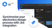
Discover how Altium 365’s Jira integration can streamline collaboration and keep projects running smoothly with real-time design updates and task tracking. Perfect for teams seeking efficiency!

Blog
•
Optimize PCB Design with Integrated BOM and CAD Systems
Discover how integrating BOM management and CAD systems can streamline your PCB design process in this insightful article. Learn how combining these tools enables smoother collaboration, reduces errors, and improves design efficiency, helping you optimize your workflows from concept to manufacturing.
Blog
•
The Essential Guide to Through-Hole Resistors
Resistors are fundamental components in electronic circuits, essential for controlling current and voltage. This article explores their basic principles, types, and key applications, helping you understand their crucial role in electronics.
Blog
•
Avoiding Costly Delays: Essential Tips for PCB Designers
Efficient PCB design is crucial for avoiding costly delays in product development. This article offers practical tips and best practices for PCB designers to streamline their workflows, minimize errors, and ensure timely project completion.
Blog
•
Understanding Signal Reflections for High-Speed Design
Signal integrity is the backbone of high-speed digital systems. In this new article by Rafał Stępień, we break down signal reflections and how to optimize your designs with effective impedance matching techniques.
Blog
•
Mastering EMI Control in PCB Design: Component Placement for EMC
In the second article of the "Mastering EMI Control in PCB Design" series Dario Fresu explores how effective component placement can reduce electromagnetic interference (EMI) in printed circuit boards. He highlights strategies such as board segregation and careful management of high-speed signals and their harmonics to ensure signal integrity and minimize emissions.
Blog
•
Signal Integrity Principles based on Altium Designer 24
Check out this article where Rafał Stępień dives into the essentials of maintaining signal integrity in high-speed digital systems. Discover key techniques like controlling signal reflections, reducing crosstalk, and designing differential pairs in Altium Designer 24 to ensure reliable and efficient PCB performance.

Blog
•
Launch of Requirements & Systems Portal in Altium 365
The Requirements & Systems Portal is now live in Altium 365! Engineers can write, manage, and verify requirements within the Altium 365 workspace. You can link your requirements directly to schematics and PCB designs to ensure all engineers are working with the latest data. Request access today!
Blog
•
Enhancing Signal Integrity in PCB Design: Key Considerations and Strategies
Looking to enhance signal integrity in your PCB designs? Check out our latest article by David Marrakchi, where he shares key strategies and best practices for achieving reliable high-speed designs.
Blog
•
Favorite Tools for BOM Review
Check out our article, where Lawrence Romine shares his top tools for conducting efficient Bill of Materials (BOM) reviews in PCB design. It highlights key features in Altium 365, Octopart, and ActiveBOM that help engineers avoid unsourceable components and streamline procurement.
Blog
•
Mastering EMI Control in PCB Design: How Signals Propagate in a PCB
As the first article in the "Mastering EMI Control in PCB Design" series from our new asset Dario Fresu, this piece explores signal propagation in PCBs, highlighting the crucial roles of impedance, dielectric materials, and trace geometry in maintaining signal integrity.
Blog
•
High-Speed PCB Design: Ensuring Signal Integrity, EMI Mitigation, and Thermal Management
Discover essential strategies for high-speed PCB design, focusing on signal integrity, EMI mitigation, and thermal management. Our latest article provides insights on managing crosstalk, optimizing grounding, and addressing thermal challenges to ensure reliable PCB performance.
Blog
•
Designing Micro-vias with Sintered Paste for Rigid-Flex Printed Circuit Boards
Designing microvias with sintered paste in rigid-flex PCBs offers enhanced electrical conductivity and mechanical strength, crucial for high-density applications. Our new article explores the benefits of sintered paste and provides essential design tips to optimize microvia performance and reliability.

Blog
•
Simple Strategies to Reach 10% PCB Cost Reduction
Our new article outlines strategies to achieve a 10% reduction in PCB costs by optimizing design and material choices, such as adjusting stack-up materials and hole sizes, using lower-cost parts, and considering single-sided assembly. These techniques help reduce expenses without sacrificing quality.

Blog
•
Say Goodbye to EDA Software Vendor Lock
Check how Altium 365 helps eliminate EDA software vendor lock by enabling multi-CAD support in the cloud. This allows users to work with different CAD file formats within a single platform, enhancing collaboration and reducing the need for additional licenses. This approach offers greater flexibility and is set to transform the industry.

Blog
•
The Ultimate Introduction to High-Speed Signal Integrity for PCB Designers
High-speed signal integrity is essential in PCB design to ensure data accuracy and system reliability. Key issues like impedance mismatches, crosstalk, and signal reflections need to be addressed through strategies such as controlled impedance traces, differential pairs, and suitable material choices. Check out our first article of the series about this topic.










Your search returns no results.


