
Main navigation

  • Home
  • Discover
  • Learning Center
  • What’s New

Second main navigation

  • Altium Community
  • Support
  • Documentation
×

Results

  • Updates
  • Blog 571
  • Video 541
  • Webinar 86
  • Playlist 53
Filters:
Tag (field_common_tag)
Blog • Aug 11, 2025
Getting Started with the GreenPAK Introduction Kit

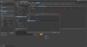
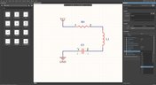
Take your first steps into mixed-signal design with the Renesas GreenPAK Introduction Kit. Ari Mahpour shows how to design, simulate, and validate a clock divider project, making it easy for beginners to start experimenting with programmable mixed-signal devices.

Read More
Embedded thumbnail for Arduino to Custom PCB: Professional Design Transformation
How-To's • Aug 7, 2025
Arduino to Custom PCB: Professional Design Transformation

Discover how to upgrade your Arduino Nano-based PCB design into a professional, custom PCB. This tutorial walks through the process of replacing development boards with individual components to create a production-ready design, using a real drone project as the example.

Start Watching
Blog • Aug 6, 2025
Smarter Electronic Part Sourcing for Automotive Purchasing Professionals

Targeted at procurement professionals in the automotive industry, the article outlines the evolving pressures of sourcing components for electrified and connected vehicles. It highlights Octopart’s ecosystem as a unified tool that centralizes availability, compliance, pricing, and lifecycle intelligence to optimize sourcing efficiency.

Read More
Embedded thumbnail for PCB Library Management: One Library or Many?
How-To's • Aug 5, 2025
PCB Library Management: One Library or Many?

This detailed guide walks you through the pros and cons of each approach and offers proven strategies for managing component data, whether you're an independent designer or overseeing libraries for an entire organization.

Start Watching
Blog • Aug 4, 2025
Stack-Up to Success: Avoid the Pitfalls

"Stack‑Up to Success" highlights how a carefully planned PCB stack‑up is foundational to preventing warpage, managing impedance, and avoiding manufacturing delays by clearly communicating layer construction, materials, and tolerance requirements to fabricators.

Read More
Embedded thumbnail for Coming Soon: Sawtooth Rounding Support for Length Tuning
New in Altium Designer 25 • Jul 31, 2025
Coming Soon: Sawtooth Rounding Support for Length Tuning

Sawtooth Rounding for Length Tuning improves signal‑path accuracy by applying controlled corner‑rounding to sawtooth geometries during both Interactive Length Tuning and within‑pair matching in the Auto Tuning engine. Discover this capability and additional innovations on our Coming Soon page.

Start Watching
Blog • Jul 30, 2025
IC Components Explained: A Comprehensive Guide to Integrated Circuits

Gain a clear understanding of the fundamental elements within integrated circuits. This guide examines their structure, function, and role in system performance, knowledge that’s vital for anyone involved in sourcing or developing electronic designs.

Read More
Embedded thumbnail for Coming Soon: Z-Axis Clearance Rule
New in Altium Designer 25 • Jul 29, 2025
Coming Soon: Z-Axis Clearance Rule

The Z-Axis Clearance Rule checks the shortest distance between copper features on different layers in a PCB design. It is available in both the Constraint Manager and the legacy PCB Rules Editor. Discover more new features in Altium on our Coming Soon Page.

Start Watching
Blog • Jul 28, 2025
Ensuring Precise Connector Alignment in Multi‑Board Manufacturing

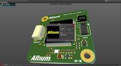
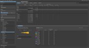
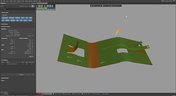
Misaligned connectors can cause major issues in multi-board assemblies. In this article, David Marrakchi shows how Altium’s 3D tools help detect and fix alignment problems early in the design process.

Read More
Embedded thumbnail for Coming Soon: Advanced Polygon Pour Engine
New in Altium Designer 25 • Jul 24, 2025
Coming Soon: Advanced Polygon Pour Engine

Now supports true arcs instead of approximated curves in copper pours. This enhanced engine marks a major advancement in the polygon pour process in Altium Designer, delivering smoother and more accurate copper shapes. Native arc rendering improves visual quality and helps ensure cleaner, more professional PCB designs.

Start Watching
Blog • Jul 23, 2025
Getting Started with the Renesas RA8D1 Evaluation Kit and Edge AI

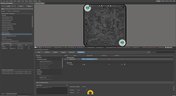
Dive into the power of Renesas’ RA8D1 MCU using the EK‑RA8D1 evaluation kit. Learn how to train, test, and deploy image‑based detection models seamlessly with Edge Impulse, and kickstart your embedded vision AI projects in minutes.

Read More
Embedded thumbnail for How to Design Rigid-Flex PCB Stackups from Scratch
How-To's • Jul 22, 2025
How to Design Rigid-Flex PCB Stackups from Scratch

Watch this tutorial to learn the fundamentals of Rigid-Flex design. We cover everything from understanding polyimide materials and adhesive layers to building complex, multi-layer Rigid-Flex constructions that are ready for manufacturing.

Start Watching
Blog • Jul 21, 2025
How to Effectively Use Jira for Hardware Development Projects

Originally built for software development, Jira has become a popular tool for agile project management across various industries. Our new article explores how hardware teams can leverage core Jira features and adapt agile principles to suit the unique needs of hardware development.

Read More
Embedded thumbnail for How to Draw Antipads - Complete Tutorial
How-To's • Jul 17, 2025
How to Draw Antipads - Complete Tutorial

Discover how to draw and define antipads in Altium with this complete tutorial. Learn three different methods for creating antipads around vias. From simple design rules to advanced polygon cutouts for both basic and complex PCB designs.

Start Watching
Blog • Jul 16, 2025
Building Supply Chain Resilience: Transforming BOM Management for Modern Electronics

Discover why top electronics companies are replacing spreadsheets with purpose-built BOM management solutions. This whitepaper outlines the risks of outdated methods, offers a readiness checklist, and explores how BOM Portal helps teams cut costs, reduce risk, and speed up development with smarter, data-driven workflows.

Read More
Embedded thumbnail for Do PCB Manufacturers Actually Look at Fabrication Drawings?
How-To's • Jul 15, 2025
Do PCB Manufacturers Actually Look at Fabrication Drawings?

Explore this in-depth tutorial featuring real fabrication drawings, stackup specifications, and drill tables - all created using Altium Designer’s Draftsman tool. Learn essential insights into PCB data management and manufacturing requirements from an industry perspective.

Start Watching
  • Show More
Tag (field_common_tag)
Article preview
Blog • Sep 8, 2020
Sharing PCB Data with Manufacturers in the Cloud

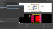
Once you’ve finished your new project and you’re ready to push it to your manufacturer, you’ll normally be stuck in an endless email chain with an engineer, or you’ll have to share cloud links with each other. The cloud sharing and design release tools in Altium Designer and Altium Concord Pro are a huge help in this area. In this post, I’m going to take an existing project I’ve worked with in a number of recent blogs, create some fabrication and assembly documentation, and finally push this data to a manufacturer using Altium Concord Pro.

Read More
Article preview
Blog • Sep 3, 2020
The Great PCB Layout "Rules of Thumb" Debate Rages On

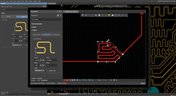
To this day, I still see many PCB layout “rules of thumb” that first became common nearly 20 years ago. Do these rules still universally apply? The answer is a firm “maybe.” The discussion around PCB layout rules of thumb is not that these rules are correct or incorrect. The problem is that the discussion around these rules often lacks context, leading to the always/never type of discussion seen in some popular forums. My goal in this article is to communicate the context behind the common PCB design rules.

Read More
Article preview
Blog • Sep 1, 2020
How to Design Your PCB Test Coupon and What You Can Test

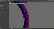
As the operating speed of components has increased, controlled impedance is becoming more common in digital, analog, and mixed-signal systems. If the controlled impedance value for an interconnect is incorrect, it can be very difficult to identify this problem during an in-circuit test. However, testing is normally performed on a PCB test coupon, which is manufactured on the same panel as the PCB. If you want to get through board spins quickly and aid future designs, you might consider designing a test coupon and keeping it handy for future designs.

Read More
Article preview
Blog • Aug 20, 2020
Altium DbLibs and Electronic Components in the Cloud with Altium Designer 20.1

Altium’s DbLib support is one of the oldest and most loved features of Altium Designer for managing electronic components and their data. They’ve been present in the software world since before I could fathom the existence of Ohm’s law. Altium 20.1’s new Component Sync feature allows you to synchronize virtually any database or database Library with Altium 365, taking advantage of both approaches strengths.

Read More
Article preview
Blog • Aug 18, 2020
What is a Schematic Netlist for Your PCB?

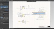
If you’ve created your next great schematic, there is a lot going on behind the scenes in your design software. A schematic netlist is one of the central pieces of information that will be used in multiple features in your design software to create a real PCB. Your schematic netlist provides both electrical connectivity information, and reflects the functional structure of your design data in a single set of data.

Read More
Article preview
Blog • Aug 13, 2020
How to Select an Inductor for a Buck Converter

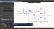
An SMPS is one of those quiet (yet electrically noisy) devices that makes your favorite electronics run smoothly. Among the numerous DC-DC converter topologies, a buck converter finds plenty of uses for stepping down the input voltage to a lower level while providing high efficiency power conversion. A common question around component selection for these power converters is how to select an inductor for a buck converter. The goal in working with an inductor and other components in a buck converter is to limit power loss to heat and while minimizing current ripple.

Read More
Article preview
Blog • Aug 11, 2020
US Department of Transportation Seeking Alternatives to GPS

GPS-capable devices range from your phone to your smartwatch; simply type in your destination and follow the directions. Simple, right? According to the Washington Post, we should all stop using GPS as it’s ruining the navigation centers of our brains. Despite the neurological effects on perception and judgment, the U.S. Department of Transportation (DOT) aims to find alternatives to GPS to provide redundancy.

Read More
Article preview
Blog • Aug 6, 2020
Bluetooth 5.1 SoC vs. Module: Which is Best for Your Design?

The list of features available in Bluetooth just got a little longer since the release of Bluetooth 5.1. If you want to incorporate a Bluetooth 5.1 SoC into your new product, you have two primary options for bringing this component into your board. The first is as an SoC that mounts to your board just like any other component. The other option is to bring a module into your new board—directly onto the surface layer. Here’s what you need to know about a Bluetooth 5.1 SoC or module in your next IoT product.

Read More
Altium 365 Getting Started User Guide - Available Now
Blog • Aug 5, 2020
Altium 365 Getting Started User Guide - Available Now

Get Started with Altium 365 with a step-by-step guide and videos to experience the most connected experience for PCB design and realization: https://my.altium.com/altium-365/getting-started/

Read More
Article preview
Blog • Aug 4, 2020
USB Power Delivery for Your Next Project

Since its introduction in the late 90s, the USB standard has never ceased to grow in popularity. There has been a growing trend toward USB being a power delivery interface with data, rather than a data interface that can supply power, as the 1.0 specification originally intended. To supply the increasing thirst for power over USB, the USB 3.0 Spec with Type-C began implementing the Power Delivery standard, which you should consider using for your next electronics project.

Read More
Article preview
Blog • Jul 30, 2020
Circuit Board Design for In-Circuit Testing

There are many types of circuit board tests available in electronics manufacturing today, each having unique goals and characteristics. This article presents guidelines at the design level (schematic and layout) to enable the use of in-circuit testing (ICT) fixtures to verify proper component assembly. These simple test fixtures allow your board to be tested as its assembled, which helps identify and remove failed boards from your production run.

Read More
Article preview
Blog • Jul 28, 2020
Planning for the Future with Cirris Systems and Altium

Technological advancements have been a hallmark of the past few decades, from the widespread adoption of internet technology to the smartphones and wireless devices we rely on every day to stay connected. Orlan Thatcher, Board Layout Specialist at Cirris Systems, could never have predicted the demand their services would generate. The company struggled with six different software platforms before switching to Altium Designer.

Read More
Article preview
Blog • Jul 23, 2020
An Introduction to NFC

I used to work in a research lab that worked primarily with RFID (Radio Frequency IDentification) and NFC (Near Field Communication) technology, particularly for the agriculture industry and cattle identification. These were very specialized fields; however, the lab also worked on projects which involved retail and various other applications for NFC. It’s an amazing technology that you might be using every day without thinking about it - building access to your mobile phone payments, for instance. 

Read More
Article preview
Blog • Jul 22, 2020
Editing Your PCB Geometry with MCAD Tools

You need to define your PCB geometry in the context of your enclosure. If your board cannot physically be assembled into the final product, it doesn't matter how well laid out it is electrically. This webinar focuses on how the MCAD CoDesigner allows you to edit your PCB in the context of a higher-level assembly, allowing you to respect the relevant mechanical constraints.

Read More
Blog • Jul 21, 2020
The PCB Fabrication Process — what Every Design Engineer Needs To Know, Part 2

In Part 1 of this article, I described the first steps that occur during the PCB fabrication process. They detailed the inner layer processing effort as well as the efforts that take place during the transition from inner layer processing to lamination. This part of the article will provide a detailed description of the lamination, drilling and plating processes.

Read More
Blog • Jul 16, 2020
The PCB Fabrication Process—What Every Design Engineer Needs To Know, Part 1

There are still a number of designers - perhaps most of them - who have never toured a PCB fabrication facility. They are also unaware of the various steps that occur during the fabrication process. The purpose of this article is to describe those steps and what transpires in each of them. Part 1 of this article focuses on inner layer processing and the steps that are done prior the lamination process.

Read More
  • Show More
Tag (field_common_tag)
Embedded thumbnail for Insert Logo or Any Images on PCB
New in Altium Designer 21 • Dec 28, 2020
Insert Logo or Any Images on PCB

In the process of designing a printed circuit board, it becomes necessary to apply additional marking. It can be a company logo, interface designation or additional information signs. For ease of creating additional markings in Altium Designer 21, the PCB editor has a new Graphics tool that allows you to insert a picture into a specified area. This tool supports any of the four formats JPG, BMP, PNG, SVG. After selecting the image, it remains to specify its quality and the tool converts the image into a region on the active layer. If necessary, you can invert the image.

Start Watching
Embedded thumbnail for Using Polygons on Power Planes
New in Altium Designer 21 • Dec 28, 2020
Using Polygons on Power Planes

Traditionally, a PCB power plane is designed as a negative, that is, the objects placed on a power plane layer become voids in the copper when the board is fabricated. This approach is used because it is more efficient to generate the output data this way, as the bulk of a plane layer is normally copper; voids in the copper are only needed in specific locations such as around non-connected pads, or as separation voids when the plane is divided into different voltage regions.

Start Watching
Embedded thumbnail for Enhanced Polar Grid Support
New in Altium Designer 21 • Dec 28, 2020
Enhanced Polar Grid Support

Component placement is one of the main steps in board design. And in specific boards of a circular shape, it is convenient to use a polar grid for the location of components. Altium Designer 21 brings several improvements to the polar grid. Now, when a component is positioned in a polar grid, its properties additionally display location coordinates relative to this grid. Using them, you can quickly arrange the components in the right places. And moving the component off the grid, polar coordinates are automatically disabled.

Start Watching
Embedded thumbnail for New PCB Length Tuning Patterns
New in Altium Designer 21 • Dec 28, 2020
New PCB Length Tuning Patterns

Length matching is a critical element of high-speed design, usually solved by carefully tuning the lengths of critical routes. This release sees extensive improvements to both single-sided and differential pair length tuning capabilities. Length tuning now supports all three popular tuning patterns: Trombone, Sawtooth, and Accordion. If you are working with lower speed or lower frequency signals, you can get away with trombone tuning. For the Trombone patterns, the polygonal area that the pattern is constructed within can be thought of as a sleeve.

Start Watching
Embedded thumbnail for Expressions Library for Frequently Used Rules
New in Altium Designer 21 • Dec 28, 2020
Expressions Library for Frequently Used Rules

When working with design rules, we often use different scopes of the rules. To simplify the repetitive process of creating advanced type rules, the new Altium Designer 21 Rule Editor has the ability to save query-based object mapping scopes in a scoped library. To do this, it is enough to export the request by clicking on it with RMB. The library is presented through the Properties panel, where custom scopes can be edited, new ones added, and later reused in other custom constraint rules.

Start Watching
Embedded thumbnail for Constraint Rule Violations
New in Altium Designer 21 • Dec 28, 2020
Constraint Rule Violations

Enabled design constraint rules are applied to the current board design through a range of mechanisms, such as live Online Design Rule Checking, the batch Design Rule Checker or selectively run from the PCB Rules and Violations panel. Violations of those constraint Rules – where the specified and scoped limits are exceeded – are indicated through board graphics, panel entries and reports. With the introduction of a new Rules Editor in Altium Designer 21, violations of these rules are now displayed in the Rules Editor itself.

Start Watching
Embedded thumbnail for Table-based Approach for Design Rules and Constraints
New in Altium Designer 21 • Dec 28, 2020
Table-based Approach for Design Rules and Constraints

Define and assign a specific list of rules and constraints to all critical design elements, such as components, nets, and LVDS.

Start Watching
Embedded thumbnail for Comprehensive Simulation Model Support
New in Altium Designer 21 • Dec 28, 2020
Comprehensive Simulation Model Support

Having accurate SPICE models is critical to the success of your simulation. Altium Designer now supports analog PSpice, LTspice, and more including generic component SPICE models for when you can’t find company models. Generic components contain Spice model parameters to simplify simulation. When you are done with simulation, quickly replace your generic components with an existing component to finish your design.

Start Watching
Embedded thumbnail for Easy to Start Simulations
New in Altium Designer 21 • Dec 28, 2020
Easy to Start Simulations

0:00 Simulation Dashboard Panel Following on from the recent introduction of an advanced new SPICE Simulation engine for Altium Designer, the latest round of Simulation updates focuses on user interface. A major component of the Altium Designer Simulation user interface updates is the introduction of the Simulation Dashboard panel. The panel offers a greatly simplified approach to checking, configuring, running and reviewing simulations.

Start Watching
Embedded thumbnail for Rigid-Flex Board Planning Mode
New in Altium Designer 21 • Dec 28, 2020
Rigid-Flex Board Planning Mode

This new release of Altium Designer 21 includes significant improvements to the Rigid-Flex board designs. Along with many bug fixes and enhancements, the next phase of Altium Rigid-Flex technology development is providing functional improvements. It is now possible to create new board regions by primitives using the appropriate command from the Design » Board Shape menu. The properties of all created regions are now displayed in the Properties panel where you can edit the name of each region and define the previously created stacks for each region of the board.

Start Watching
Embedded thumbnail for Component Pin to Multiple Pad Mapping
New in Altium Designer 21 • Dec 28, 2020
Component Pin to Multiple Pad Mapping

This release introduces flexible pin to pad mapping capabilities for managed components. Enhancements to the Single Component Editor and the introduction of a new Pins panel allow component symbol pins to be mapped to any component footprint pad, or any number of footprint pads. The Pins panel, opened from the editor's button, allows the default one-to-one pin-pad mapping to be changed to a custom relationship, such as one pin being connected to multiple footprint pads – or any other non-aligned pin to pad number relationship.

Start Watching
Embedded thumbnail for Enhanced Navigation by Nets in Schematic - Altium Designer 21 What's New
New in Altium Designer 21 • Dec 28, 2020
Enhanced Navigation by Nets in Schematic - Altium Designer 21 What's New

Altium Designer 21 brings many improvements to the schematic editor aimed at visualizing circuits and improving navigation through them in multi-sheet and hierarchical designs. By holding Alt and clicking on the net, All schematic instances of the net are highlighted, while other objects are dimmed, to visibly indicate the signal/power propagation in the design using one simple action. The changes also affected the Identification of net names. Now logical and physical names of a net are displayed in the properties panel as well as when you hover over this wire.

Start Watching
Embedded thumbnail for Intelligent Schematic Insights
New in Altium Designer 21 • Dec 28, 2020
Intelligent Schematic Insights

Due to advances in the format and compilation of the Altium Designer data model, schematic Wire objects have now evolved from a simple graphical object to a more advanced form that can be directly associated with electrical parameters. As a result, the Wire mode of the Properties panel has been updated to provide an expanded set of options and a wider range of information. The new additions include a General section for net parameter options and information, and a Parameters section that lists the User Parameters, Rules and Net Classes associated with the Wire's assigned net.

Start Watching
Embedded thumbnail for Start Your Schematic with Generic Components
New in Altium Designer 21 • Dec 28, 2020
Start Your Schematic with Generic Components

It can be challenging to pick the right components when working on a new schematic. You have to consider availability, cost, and various parametric requirements. What if you could place a component to complete your design and quickly replace it when you are ready for layout? Introducing new Generic Components. Simply provide generic parameters, such as Value or Footprint, to greatly speed-up your capturing process while eliminating the need to search for specific Part Numbers or creating a needed component from scratch.

Start Watching
Embedded thumbnail for MCAD CoDesigner Overview
Working with MCAD CoDesigner extension • Dec 21, 2020
MCAD CoDesigner Overview

The MCAD CoDesigner in Altium Designer allows for seamless design transfer between the Electrical and Mechanical designers. In this overview, we’ll show you how to transfer from Altium Designer to your CAD tool of choice, then how to resize the board, add mounting holes, add a new connector, and update the board design in Altium Designer.

Start Watching
Embedded thumbnail for Bringing an MCAD Enclosure to ECAD
Working with MCAD CoDesigner extension • Nov 16, 2020
Bringing an MCAD Enclosure to ECAD

The Altium Designer MCAD CoDesigner panel and extension make it easy to move a 3D enclosure model from your MCAD tool to Altium Designer. We'll show you how and what to watch out for while your transferring your enclosure model to Altium Designer.

Start Watching
  • Show More
Tag (field_common_tag)
BOM Editor
On-Demand Webinar • Jun 13, 2024
BOM Editor
Watch Now
Simulation
On-Demand Webinar • May 24, 2024
The Value of Upgrading: Time and Financial Advantages of Recent Altium Versions
Learn how features such as PCB Layout Replication, Auto Tuning, and Simulation are making design processes more efficient and effective.
Watch Now
Constraint Manager
On-Demand Webinar • May 22, 2024
Constraint Manager
Watch Now
Configurable Workflows In-App On Demand
On-Demand Webinar • May 20, 2024
Configuring Electronics Development Workflows That Really Work: Best Practices
Watch the webinar to understand the impact of disjointed workflows on project timelines, product quality, and cross-functional collaboration. Learn how configurable workflows can help you accelerate innovation and maintain competitive advantage.
Watch Now
Iterate Faster in Complex Engineering Projects Webinar Cover
On-Demand Webinar • May 15, 2024
Iterate Faster in Complex Engineering Projects
Learn how Valispace is transforming the world of requirements and systems engineering, enabling teams to do super fast design iterations and develop quality products while ensuring they comply with standards and regulations.
Watch Now
Z2Data Webinar Cover
On-Demand Webinar • Apr 25, 2024
Bridge the Information Divide: Altium 365 Meets Z2Data
Watch the webinar to learn how Z2Data can help you build resilience in engineering, compliance, and procurement through the comprehensive supply chain and component data.
Watch Now
Data management
On-Demand Webinar • Apr 22, 2024
Mastering Data Management with Altium Designer 24
Join our webinar to learn how easy it is to manage, access, and synchronize your data with Altium Designer 24.
Watch Now
BOM Portal Webinar Cover
On-Demand Webinar • Apr 19, 2024
Bridge the Gap Between Engineering and Procurement: Altium 365 BOM Portal
Watch the webinar to learn how to make informed decisions and mitigate supply chain risks with Altium 365 BOM Portal, BOM management application purpose-built for electronics engineering and procurement. Improve your time to market and proactively manage electronic component supply chain risks.
Watch Now
Enterprise Subscription
On-Demand Webinar • Apr 18, 2024
Introduction to Altium 365 Enterprise Subscription Level
Watch Now
Introduction to Altium 365 Enteroruse Subscription
On-Demand Webinar • Apr 18, 2024
Introduction to Altium 365 Enterprise Subscription Level
Watch Now
AD Subscription levels
On-Demand Webinar • Apr 18, 2024
Introduction to Altium 365 Pro Subscription
Watch Now
Altium 365 Standard Subscription
On-Demand Webinar • Apr 18, 2024
Introduction to A365 Subscription Levels - Standard
Watch Now
Harness Design
On-Demand Webinar • Apr 18, 2024
Harness Design Introductory Demo
In this video, we explore Altium Designer's integrated harness design features, showing how it simplifies creating wiring harnesses within the same environment as PCB and system design.
Watch Now
Introduction to Altium Designer Subscription Levels
On-Demand Webinar • Apr 18, 2024
Introduction to Altium Designer Subscription Levels
Whether customer designs are simple or complex, and your customers work solo or in a team,
Altium has a solution for every engineer or enterprise. Altium offers three subscription levels, Standard, Pro and Enterprise.
Watch Now
MCAD CoDesigner
On-Demand Webinar • Apr 18, 2024
MCAD CoDesigner: ECAD-MCAD Collaboration
This video introduces the MCAD CoDesigner feature in Altium Designer, a powerful tool designed to enhance collaboration between electrical and mechanical engineers.
Watch Now
SiliconExpert Integration Altium 365
On-Demand Webinar • Apr 11, 2024
Design with Confidence: Altium 365 Meets SiliconExpert
Watch the webinar to learn how SiliconExpert Integration in Altium 365 can optimize your workflows and elevate your design process.
Watch Now
  • Show More
Tag (field_common_tag)
Loading
Loading...
Share link
Share with
Search by Update
Version
Update
25 26 24 23 22
25.0 25.1 25.2 25.3 25.4 25.5 25.6 25.7 25.8 25.9
26.1 26.2
24.10 24.9 24.8 24.7 24.6 24.5 24.4 24.3 24.2 24.1 24.0
23.11 23.10 23.9 23.8 23.7 23.6 23.5 23.4 23.3 23.2 23.1 23.0
22.11 22.10 22.9 22.8 22.7 22.6 22.5 22.4 22.3