News & Updates

Blog
•
Increasing PCB Prototype Iteration Speed in the Cloud
How often have you started down the PCB development process and been bogged down by time-consuming administrative tasks? Once you get ready for production, working through a design review and correcting any DFM problems takes its own share of time. With hastening product development timelines and shorter product life cycles comes the pressure to increase PCB prototype iteration speed without sacrificing cost or quality. So how can PCB design teams keep their development schedules on track without sacrificing quality or risking a failed prototyping run?

Blog
•
Why you should be using Concord Pro?
A journey of a thousand miles begins with a single step, or so the aphorism goes. I think it’s worth noting that the first step is the most difficult to take. Analysis Paralysis is especially true when dealing with a new software package, including the recent release of Concord Pro. The recent version has brought with it a deluge of interest and enthusiasm in such a phenomenal tool. But I must say, Altium hit this one out of the park.

Blog
•
What Types of EMI Filters are Best for Passing EMC Certification?
When you need to pass EMC certification and your new product is being crippled by a mysterious source of EMI, you’ll probably start considering a complete product redesign. Your stackup, trace geometry, and component arrangement are good places to start, but there might be more you can do to suppress specific sources of EMI. There are many different types of EMI filters that you can easily place in your design, and that will help suppress EMI in a variety of frequency ranges.
Blog
•
An Overview Of PCB Outer Layer Processing
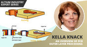
Previously, I described the PCB fabrication operations relative to inner layer processing, lamination, drilling, and plating. The last step in the process is outer layer processing which is described below. Once the desired plated copper thickness of a PCB has been achieved, it’s necessary to etch away the copper between the features in order to define the outer layer pattern.

Blog
•
How Do Pads and Vias Impact Total Capacitor Parasitic Inductance?
There are many factors at play in determining the impact of inductance on high-frequency power distribution systems. Two topic areas, inductance of the decoupling capacitor and inductance of the power planes, were addressed in earlier articles. This article will focus on the inductance of the capacitor footprint and via inductance from the capacitor footprint back to the PCB power planes.

Blog
•
Analyzing Crosstalk on FIFO and DDR4 Parallel Bus Interfaces
High-speed buses, whether single-ended or differential, can experience any number of signal integrity problems. A primary problem created by propagating signals is crosstalk, where a signal superimposes itself on a nearby trace. The industry-standard PCB design tools in Altium Designer® already include a post-layout simulator for examining crosstalk. Still, you can speed up crosstalk analysis in parallel buses when you use a powerful field solver.


Blog
•
Amplifier Stability at High Frequencies and Stray Capacitance
Any time-dependent physical system with feedback and gain has conditions under which the system will reach stable behavior. Amplifier stability extends these concepts to amplifiers, where the system output can grow to an undesired saturated state due to unintended feedback. If you use the right design and simulation tools, you can easily account for potential instability in your circuit models before you create your layout.


Blog
•
Working with Design Variants
The concept of design variants entails taking a single PCB design, and then on the assembly side, modifying specific components used in the design. Either by not installing, not installing, or choosing alternate components as replacements on a specific assembly to ultimately create different end products. In that way, you could support multiple product lines. This article describes the approach to working with variants.

Blog
•
Setting Up Concord Pro Revisions and Lifecycle
Before anything else, some advice. The revisions and lifecycle are an area that takes some planning. It used to be that Concord Pro was primarily for components, but now it has gone far beyond that. With the ability to store and manage many other items, including your various templates, projects, even PDF documents, not everything will have the same revision scheme. Concord Pro is so powerful that it can handle any revision scheme you’d want to set up.


Blog
•
How to Successfully Design a BGA
Whether the board will be placed in a high pressure vessel or underwater, your design will need to withstand pressure to avoid failure. On the enclosure side, your vessel should be rated up to a certain pressure and may require frequent cycling to prevent implosion. On the electronics side, component selection and layout (especially at high voltage) become critical to preventing failure and ensuring reliability.

On-Demand Webinar
•
Editing Your PCB Geometry with MCAD Tools Webinar
You need to define your PCB geometry in the context of your enclosure. If your board cannot physically be assembled into the final product, it doesn't matter how well laid out it is electrically. This webinar focuses on how the MCAD CoDesigner allows you to edit your PCB in the context of a higher-level assembly, allowing you to respect the relevant mechanical constraints.

Blog
•
Altium Designer 20.2 Update 1 is now available
The first update of Altium Designer 20.2 and Altium NEXUS Client 3.2 is now available. You can update through the Altium Designer update system ("Extensions and Updates") or download fresh builds from the Downloads section of the Altium website. Click on "Read More" to see a list of all changes in this update.

Blog
•
How Copper Foil Roughness Affects Your Signals and Impedance
The history of engineering, both electrical and mechanical, is littered with approximations that have fallen by the wayside. These approximations worked well for a time and helped advance technology significantly over the decades. However, any model has limits on its applicability, and the typical RLCG transmission line model and frequency-independent impedance equations are no different. Copper foil roughness modeling and related transmission line impedance simulations are just one of many areas in which standard models cannot correctly treat signal behavior.

Blog
•
What is Burn-in Testing for Electronics?
Once you’re planning for production of any new board, you’ll likely be planning a battery of tests for your new product. These tests often focus on functionality and, for high speed/high frequency boards, signal/power integrity. However, you may intend for your product to operate for an extreme period of time, and you’ll need some data to reliably place a lower limit on your product’s lifetime. In addition to in-circuit tests, functional tests, and possibly mechanical tests, the components and boards themselves can benefit from burn-in testing.
Blog
•
PCB Design for Testability to Ensure High Yield and Quality
If you remember your days in school, then you probably remember the feeling of happiness and celebration when you pass a big exam. You’ll feel the same sense of adulation when your board spin passes a barrage of pre and post assembly tests, but a complex design might not reach that stage unless you implement the right design for testability methods. There are some simple steps that can help your manufacturer identify and quickly implement important bare-board and in-circuit testing (ICT), especially on critical circuit blocks.

Blog
•
Top Tips from Experienced Flex Designers
This article describes the best hints and tips for designers of rigid-flex circuits. These tips include choosing the most appropriate material, suggestions for coordinating the PCB with the manufacturer, and a set of rules to be followed while PCB design.
NEW

Blog
•
Why Modern Electronics Teams Are Moving to a Cloud ECAD Platform
Great products are built by connected teams, not disconnected tools. This article shows how cloud ECAD platforms enable real-time co-design, structured design reviews, and seamless collaboration across engineering, manufacturing, and supply chain teams.
NEW
Blog
•
10 Questions to Ask Your Fabricator Before Submitting a Rigid-Flex Design
A five-minute conversation with your fabricator could save weeks of redesign. Discover the ten questions that can improve manufacturability, boost yield, and help your rigid-flex project succeed on the first build.
Blog
•
Who Needs Integrated Electronic Component Search
Finding the right component shouldn't mean searching through dozens of websites and datasheets. This article shows how integrated component search helps engineers select parts faster while reducing sourcing risks and design delays.

Blog
•
How BOM Portal Supports R&D and Procurement with DFM & DFC Analysis Throughout the Entire Product Lifecycle
The best sourcing decisions happen when procurement is involved early. This webinar demonstrates how BOM Portal gives both engineering and procurement access to live lifecycle, pricing, compliance, and availability data to drive smarter decisions from prototype through production.
Blog
•
How to Design a PCB: From Schematic Capture to Manufacturing
This article walks through the complete PCB design workflow, from schematic capture and component selection to layout, design reviews, and manufacturing documentation. It highlights the key decisions at each stage that help engineering teams produce reliable, manufacturable products.
Blog
•
5 Power Integrity Myths: AC Edition
The biggest threat to your power integrity might be outdated design advice. This article challenges five common AC power integrity myths and shows what really matters when designing today's high-speed PCBs.

Blog
•
Your Design Data Has Zero Defense
Your design data may be more exposed than you think. This webinar shows how to identify common security gaps and secure engineering workflows with centralized access control and governance.
Blog
•
Flex Circuit Coverlay: Design with Lamination Processes In Mind
Your flex PCB may look perfect in CAD but coverlay doesn't stay perfectly still during manufacturing. This article reveals why designing for lamination behavior is one of the most important steps in building reliable flex circuits.

Blog
•
Integrated PCB Design vs. Legacy Point Tools: What’s the Real Cost?
As hardware development grows more collaborative, disconnected point tools can introduce data inconsistencies, traceability gaps, and costly coordination challenges. This article examines how integrated PCB design environments connect design, mechanical, supply chain, and review workflows to improve efficiency throughout the product lifecycle.

Blog
•
Make Better Design Decisions with Signal and Power Integrity Insight
Signal integrity and power integrity are closely connected, with problems in one often affecting the other as designs become faster and more complex. This webinar explains how integrated analysis workflows help engineers evaluate PDN performance, identify potential issues early, and improve overall design quality.

Blog
•
Optimizing Your Electronics Product Design Workflow and Eliminating Bottlenecks
Every manual handoff adds time and risk to the product development process. This article shows how modern design workflows automate routine tasks, improve data visibility, and help engineering teams focus on innovation instead of administration.
Blog
•
Avoid Cross-Board Signal Integrity Issues in High-Performance Multiboard PCB Designs
Your signal may be perfect on the PCB and fail the moment it crosses a connector. This article explores the hidden SI challenges in multi-board systems and how engineers can eliminate them before they become costly debugging sessions.
Blog
•
Proto-BOM in Minutes: How BOM Portal Accelerates Component Selection
Still building BOMs the hard way? Discover how modern workflows can help you create a prototype-ready BOM faster while improving visibility into pricing, availability, and risk.

Blog
•
How to Manage Power Integrity and EMI in Complex Multiboard Systems
This article examines the challenges of maintaining power integrity and controlling EMI in complex multiboard systems. It provides practical strategies for managing return paths, connector transitions, and power distribution across interconnected assemblies.

Blog
•
Agile Teams: From Design Tool to Product Development Platform
Learn how Agile Teams evolves beyond traditional PCB design workflows to support connected product development. This webinar explores how centralized data, collaboration tools, and governance capabilities help teams accelerate delivery while maintaining control.

Blog
•
Benefits of Using an Integrated Design Environment for PCB Development
Using separate tools often creates inefficiencies and increases the risk of mistakes. This article explains how integrated design environments streamline workflows by keeping design data connected and accessible.













Your search returns no results.


