News & Updates

NEW

Blog
•
Flex Material Realities: Why You Can't Always Get the Dielectric Thickness You Want
That perfect dielectric thickness in your design software might not exist on the production floor. Learn why flex PCB materials come with practical limitations and how early collaboration with your fabricator can help keep your design on track.

NEW

Blog
•
What Makes a Product Ready for Mass Manufacturing? What Design and Supply Chain Teams Need to Know
This article examines the key factors that determine whether a product is ready for mass production. It explores how design maturity and supply chain readiness work together to ensure a product can be manufactured at scale while meeting quality, cost, and schedule requirements.

Blog
•
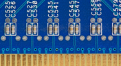
UHDI Copper Plating: What Designers Need to Understand About the Process
Your microvias might pass electrical testing and still hide a reliability problem. Explore the copper plating challenges behind Ultra HDI designs and learn why via geometry, copper fill, and first-article inspection deserve attention before production.



Blog
•
Flex Circuit Termination: What Happens at the Edge Matters More Than You Think
Flex circuit reliability depends on more than the bend zone, the termination area can be equally critical. This article explores how ZIF tails, soldered connections, stiffeners, coverlay placement, and fabrication documentation influence the reliability of flex circuit terminations.


Blog
•
When Quick-Turn Rigid-Flex Goes Wrong: The 3 Most Common Root Causes
Quick-turn rigid-flex builds can fail for reasons that are easy to overlook. Learn how to avoid three of the most common causes: stackup gaps, poorly defined transition zones and unexpected material behavior, and build more reliable rigid-flex designs from the start.


Blog
•
Optimize Performance and Design Flexibility with Structural Electronics
Structural electronics merges the PCB and mechanical enclosure into a single three-dimensional design. This article explores how this approach can improve design flexibility, thermal management, and EMI shielding while requiring closer collaboration between electrical and mechanical engineers.


Blog
•
Design for PCB Inspection in Ultra HDI
As PCB features become smaller and more densely packed, inspection becomes a critical part of the design process. This article explains how design choices and inspection planning can help ensure Ultra HDI boards can be reliably verified at production scale.

Blog
•
A Smarter Way to Manage Electronics Development
Discover how engineering managers keep large, cross-functional teams aligned and productive. This guide explores structured collaboration, repeatable workflows, and clear visibility throughout the entire product lifecycle from initial requirements to field support.


Blog
•
Ultra HDI Is Changing What “Assembly-Friendly” Looks Like
As component pitch decreases, even small manufacturing variations can consume a significant portion of the available design margin. This article explains how tolerance stacking, solder paste deposition, inspection limitations, and rework challenges can affect assembly reliability in Ultra HDI designs.
NEW
Blog
•
Flex Material Realities: Why You Can't Always Get the Dielectric Thickness You Want
That perfect dielectric thickness in your design software might not exist on the production floor. Learn why flex PCB materials come with practical limitations and how early collaboration with your fabricator can help keep your design on track.
NEW
Blog
•
What Makes a Product Ready for Mass Manufacturing? What Design and Supply Chain Teams Need to Know
This article examines the key factors that determine whether a product is ready for mass production. It explores how design maturity and supply chain readiness work together to ensure a product can be manufactured at scale while meeting quality, cost, and schedule requirements.
Blog
•
UHDI Copper Plating: What Designers Need to Understand About the Process
Your microvias might pass electrical testing and still hide a reliability problem. Explore the copper plating challenges behind Ultra HDI designs and learn why via geometry, copper fill, and first-article inspection deserve attention before production.
Blog
•
Flex Circuit Termination: What Happens at the Edge Matters More Than You Think
Flex circuit reliability depends on more than the bend zone, the termination area can be equally critical. This article explores how ZIF tails, soldered connections, stiffeners, coverlay placement, and fabrication documentation influence the reliability of flex circuit terminations.
Blog
•
When Quick-Turn Rigid-Flex Goes Wrong: The 3 Most Common Root Causes
Quick-turn rigid-flex builds can fail for reasons that are easy to overlook. Learn how to avoid three of the most common causes: stackup gaps, poorly defined transition zones and unexpected material behavior, and build more reliable rigid-flex designs from the start.
Blog
•
Optimize Performance and Design Flexibility with Structural Electronics
Structural electronics merges the PCB and mechanical enclosure into a single three-dimensional design. This article explores how this approach can improve design flexibility, thermal management, and EMI shielding while requiring closer collaboration between electrical and mechanical engineers.
Blog
•
Design for PCB Inspection in Ultra HDI
As PCB features become smaller and more densely packed, inspection becomes a critical part of the design process. This article explains how design choices and inspection planning can help ensure Ultra HDI boards can be reliably verified at production scale.
Blog
•
A Smarter Way to Manage Electronics Development
Discover how engineering managers keep large, cross-functional teams aligned and productive. This guide explores structured collaboration, repeatable workflows, and clear visibility throughout the entire product lifecycle from initial requirements to field support.
Blog
•
Ultra HDI Is Changing What “Assembly-Friendly” Looks Like
As component pitch decreases, even small manufacturing variations can consume a significant portion of the available design margin. This article explains how tolerance stacking, solder paste deposition, inspection limitations, and rework challenges can affect assembly reliability in Ultra HDI designs.

Blog
•
How Design Review Automation Saves Hours (and Headaches) Per Project
Design review automation helps teams spend less time managing feedback and more time improving the design. This article explores how centralized comments, structured checklists, action tracking, and approval workflows can make reviews faster, more consistent, and easier to close.

Blog
•
Comparing Flex and Rigid-Flex PCBs: When to Use What?
This article compares flex and rigid-flex PCBs across key design and manufacturing considerations, including cost, bend radius, impedance, and assembly complexity. It explains how choosing the right construction early can help reduce design risks and ensure better manufacturability.

Blog
•
The Security and Speed of Cloud-Based Electronics Design for Engineering Teams
Security shouldn't be the reason your engineering team slows down. This article explores how cloud-based design platforms can turn secure access, governance, and IP protection into an enabler of faster collaboration rather than another development bottleneck.

Blog
•
PCB Assembly Outputs
The right PCB assembly outputs turn a finished design into a buildable product. This article covers the essential manufacturing files and DFA considerations that help ensure assemblers have the information they need for accurate, reliable production.

Blog
•
Holistic Engineering Management in Electronic Design
This webinar explores how engineering leaders can gain greater visibility and control across complex electronic design workflows. Discover how connected processes and centralized design data help teams reduce risk, improve collaboration, and deliver projects on time.

Blog
•
PCB Design Variants: Managing Multiple PCBA Versions
Product variations often require different component populations, alternate parts, or configuration settings while keeping the underlying PCB design unchanged. This article explains how structured variant management keeps these differences organized and ensures each configuration has the correct BOM and manufacturing outputs.

Blog
•
8 Common DFM Problems PCB Design Rules Catch Before Fab
Preventing DFM problems starts before fabrication not during the fab review. This article covers eight common PCB manufacturing issues and the design rules that help engineers identify and resolve them early.






On-Demand Webinar
•
Jun 12, 2025
Proactive Lifecycle Management: Preventing Obsolescence Before It Hits


On-Demand Webinar
•
Apr 23, 2025
Collaborative Design Review: Ensuring Quality from Schematics to Supply Chain

On-Demand Webinar
•
Apr 22, 2025
From Prototype to Production: Optimizing BOM Costs Without Compromising Quality with Part Analytics



On-Demand Webinar
•
Apr 9, 2025
Component Selection in Altium Designer: Making Data-Driven Decisions with Data Integrations

On-Demand Webinar
•
Mar 25, 2025
Unlocking the full potential of your design team with Altium's enterprise solution



On-Demand Webinar
•
Jan 24, 2024
Discover How Altium Designer 24 Revolutionizes Team Dynamics in PCB Design


