News & Updates


Blog
•
PCB Via Size and Pad Size Guidelines
There are some aspects of PCB design and layout that seem deceptively simple, and yet they have a complex answer that is related to many important aspects of manufacturing. One of these design aspects is the match between PCB via size and pad size. Obviously, these two points are related; all vias have a landing pad that supports the via and provides a place to route traces into a via pad. However, there are some important sizing guidelines to follow when the matching pad and via sizes, and this match is an important element of DFM and reliability.
Blog
•
Differential Microstrip Impedance Calculator
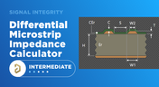
Are you looking for a free tool that you can use to calculate the impedance of differential microstrips? We created a simple tool you can use to calculate differential microstrip impedance for a given geometry and dielectric constant. If you’ve been looking for an accurate differential microstrip impedance calculator, then the calculator below is certainly one of the best free tools you’ll find on the internet before you start using field solvers to determine differential pair impedance.


Blog
•
Getting Through a PCB DFM Check
In this article, we’ll discuss the key design features to implement, and steps to take prior to fabrication that will help prevent some common DFM problems. I’ll also provide examples of where I commonly see these PCB DFM problems in signal integrity circuits.


Blog
•
What is Spreading Inductance?
If you’re working with a high-speed digital component, there are some simple power integrity rules that should be followed. However, there is one quantity that is sometimes ignored when building a PDN impedance simulation: the spreading inductance of your plane pair. Here are some points designers should know about the spreading inductance of a plane pair.


Blog
•
PCB Design Basics for New Designers
In this article, I’ll present some design basics that every new designer should follow to help ensure their design process is successful. Some of these points may challenge the conventional view of how circuit boards are constructed, but they are intended to help balance low noise signaling, manufacturability, and ease of solving a layout.

Blog
•
Selecting Materials for High Voltage PCB Design and Layout
High voltage PCBs are subject to certain safety and reliability concerns that you won’t find in most other boards. If your fabrication house specializes in high voltage PCBs and keeps materials in stock, they can likely recommend a material set, as well as a standard stackup you might use for certain voltage ranges and frequencies. If you need to choose your own materials, follow the tips below to help you narrow down to the right material set.


Blog
•
When to Use Tented Vias in Your PCB Layout
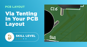
There are some guidelines I see many designers implement as a standard practice, often without thinking about it. Some of these practices are misunderstood or implemented without best practices. Others are implemented without thinking about the potential problems. One of these is the use of tented vias, which is sometimes implemented in a PCB layout by default. Is this always the right practice?

Blog
•
How to Impedance Match and Terminate Capacitive Loads
The idea of a purely capacitive load is something of a fallacy. Yes, capacitors exist, but all capacitors are non-ideal, and it is this deviation from a theoretical capacitance that determines how to impedance match a load that exhibits capacitive behavior. Let’s take a look at this important aspect of interconnect design and see what it really means to terminate a capacitive load.

Blog
•
Using Altium 365 Over Your Vanilla Version Control System
There are all sorts of version control systems out there that people have been using with their PCB design software. As discussed in Why Use a Version Control System, we looked at different options ranging for local hard drive storage to sophisticated online revisioning systems. In this article we will be reviewing the differences between a standard VCS and Altium 365.
Blog
•
Why Use a Version Control System in PCB Design
Version Control Systems (VCS) have been around for many decades within the software world but can be surprisingly new to some folks in the electronics design industry. This article will cover what a VCS is, what it does, and why you should be using one for your PCB design projects.
Blog
•
The Critical Role of Constraint-Based PCB Design in Modern Electronics
A constraint-based approach to PCB design is crucial in today's electronics industry. This article delves deeper into this complex and interesting topic, exploring various types of constraints, their advantages, and providing guidance on implementing them into your PCB design process.
Blog
•
Pi.MX8 Project – Introduction and Overview
Do you have extensive knowledge about the Pi.MX8 module? We're excited to introduce a new series of articles focusing on an innovative approach to utilizing this module. In this inaugural chapter, we provide insights into the preparation for this project and detail the elements that will be used.

Blog
•
How to 'Shift Left' and Connect Procurement and Engineering? Altium 365 BOM Portal Step-by-Step
Learn why BOM management is critical for both procurement managers and electronic engineers. Altium 365 BOM Portal helps to bridge the gap between these worlds. Discover how!
Blog
•
Altium 365 Assembly Assistant: Available Now in the Altium Store
Happy New Year! 🎉 We are thrilled to announce that the Altium 365 Assembly Assistant is now officially released and available for direct purchase through the Altium Store.

Blog
•
Simple Documentation for Hand PCB Assembly
Creating documentation for hand PCB assembly does not prevent the same documentation from being utilized to assist in automated PCB assembly. Learn more about the optimal format for this data to enhance both your hand PCB assembly and overall assembly processes.
Blog
•
Constraint Manager: Precision in Every Detail
Explore the powerful features of Altium Designer 24! Experience Constraint Manager and revolutionize your PCB design with reusable constraint sets, schematic-to-board rule transition, easy class and differential pair grouping, and more.

Blog
•
Accelerate Last-Minute Design Changes with Altium 365
Curious about how to solve production blockers before they derail your product launch? Explore how Altium 365® can help you swiftly manage last-minute design changes.
Blog
•
Design Phase – Lid Assembly Electronics Part 1
We are advancing our Open Source Laptop project to the next stage: assembling lid electronics. In the first part of this phase, we are focusing on the electronics and PCB design of the webcam module.
Blog
•
3 Common Challenges Stopping Your Production Line
The efficiency of production lines is crucial for any successful hardware product development. However, some challenges derail these processes. Do you face these problems, too? Let’s find out!
Blog
•
Explore New Possibilities with True 3D-MID Design
3D-MID technology seamlessly integrates electrical circuits with three-dimensional mechanical parts. This unique fusion of functionality unlocks a myriad of possibilities across various application areas. Explore more about this innovative feature, available in Altium Designer 24, to delve into the fascinating world of the 3D design process.
Blog
•
Strategies to Minimize PCB Damage
The PCB design process is always an exciting journey for a designer or the founder of a project. The first run of it can be breathtaking. In this article, we delve into strategies for minimizing PCB damage in the case of an exemplary circuit.

Blog
•
Fragmented Feedback Loops: The Hidden Cost in PCB Design and Testing
Explore the hidden impact of fragmented feedback loops in PCB design and testing. Check how minor communication gaps lead to significant financial burdens and learn how to address them.

Blog
•
Altium 365 GovCloud 101: Everything You Need to Know
Would you like to improve the protection of your data? Altium 365 GovCloud can help you achieve these goals. It’s a version of Altium 365, engineered to meet the stringent demands of US government regulations.
Blog
•
Design Phase – Lid Assembly Mechanics Part 3
We are heightening the anticipation for our Open Source Laptop project. In this chapter, we delve into the ambient light sensor module. Learn more about how to implement it into this project.
Blog
•
PCB CoDesign: Design Faster Together
Experience accelerated design collaboration with PCB CoDesign, exclusively available on Altium Designer starting from December 13th. This innovative feature adopts a collaborative approach by seamlessly integrating schematic and PCB design, enabling multiple engineers to work on the same project. Explore this cutting-edge feature on our newly launched page dedicated to its functionalities.

Blog
•
6 Steps to Accelerate the Development of Complex Products
Learn the key lessons from the presentation at Iteration22; “Joe Justice, Wikispeed - Everyone Must Be a Chief Engineer at SpaceX.” Read on and discover how to speed up the development of complex products.
















Your search returns no results.


