News & Updates
Blog
•
Avoid Cross-Board Signal Integrity Issues in High-Performance Multiboard PCB Designs
Your signal may be perfect on the PCB and fail the moment it crosses a connector. This article explores the hidden SI challenges in multi-board systems and how engineers can eliminate them before they become costly debugging sessions.

Blog
•
Proto-BOM in Minutes: How BOM Portal Accelerates Component Selection
Still building BOMs the hard way? Discover how modern workflows can help you create a prototype-ready BOM faster while improving visibility into pricing, availability, and risk.

Blog
•
How to Manage Power Integrity and EMI in Complex Multiboard Systems
This article examines the challenges of maintaining power integrity and controlling EMI in complex multiboard systems. It provides practical strategies for managing return paths, connector transitions, and power distribution across interconnected assemblies.

Blog
•
Agile Teams: From Design Tool to Product Development Platform
Learn how Agile Teams evolves beyond traditional PCB design workflows to support connected product development. This webinar explores how centralized data, collaboration tools, and governance capabilities help teams accelerate delivery while maintaining control.

Blog
•
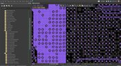
Benefits of Using an Integrated Design Environment for PCB Development
Using separate tools often creates inefficiencies and increases the risk of mistakes. This article explains how integrated design environments streamline workflows by keeping design data connected and accessible.

Blog
•
Enterprise vs. Midsize PCB Design Software: What Actually Changes at Scale
PCB design challenges change significantly as organizations scale. This article explores the key differences between mid-size and enterprise design environments, from collaboration and governance to data management and workflow automation.


Blog
•
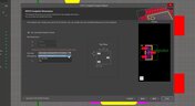
BOM Portal vs BOM Tool: What Changes When You Upgrade
Not all BOM solutions work the same way. This article explains the key differences between BOM tools and BOM portals, and why real-time data and collaboration are becoming essential for modern electronics development.

Blog
•
Altium vs KiCAD: Built to Scale From First Board to Full Product
Starting with a simple board today doesn't mean your next project will stay simple. Learn how Altium Designer and KiCAD compare when designs become more complex, teams get larger, and products move toward manufacturing.

Blog
•
Eliminate the Design-to-Production Gap with Agile Teams + Duro
Learn how Agile Teams and Duro connect design and production workflows through a unified system of record. This webinar shows how structured change management and automated data synchronization help teams reduce errors and accelerate product releases.

Blog
•
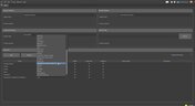
Agile Hardware Development: How to Scale Speed Without Losing Control
Agile hardware development isn’t just about working faster, it’s about working together in real time. This article explores how shared environments for ECAD, MCAD, sourcing, and requirements management eliminate handoff delays and improve decision-making across teams.

Blog
•
How Reusable Parameters in Requirements Reduce Errors and Speed Up Iterations
Verification becomes much easier when requirements and system performance data stay connected automatically. This article explains how reusable parameters and V&V rules help teams detect violations earlier and validate designs with greater confidence.


Blog
•
Complex Engineering Projects Leverage Multiple ECAD/MCAD Formats
This article explores how modern engineering teams manage complex projects involving multiple ECAD, MCAD, and manufacturing file formats across distributed workflows. It highlights the importance of design authority, disciplined revision control, and bidirectional collaboration to ensure accurate integration between PCBs and mechanical systems.

Blog
•
Streamlining Component Selection for Long Product Lifecycles
Electronic parts may now cycle from launch to end-of-life in just a few years, but many systems are expected to serve for 10–20+ years. Here’s how to build a component selection process that aligns engineering, procurement and design for longevity and stability.
Blog
•
Using ECAD Software to Track Part Availability During PCB Design
As component lead-times extend and obsolescence becomes a persistent threat, PCB projects demand more than schematic capture and layout tools alone. This article details how ECAD software with embedded supply-chain intelligence can: unify engineering and procurement teams; provide visibility into stock levels, lead times and alternates; and enable proactive risk mitigation within the design loop.

Blog
•
PCB Design Data Management Tips for Multi-Board Projects
In complex electronic systems, managing data from multiple printed circuit boards can quickly become a logistical challenge. This article outlines a structured workflow for handling both board-level and assembly-level design outputs, ensuring clarity and consistency across fabrication, assembly and product-level documentation.

Blog
•
6 Areas Your PCB Design Reviews Should Focus On
Learn the six essential topics every electronics team should address in design reviews to improve quality, avoid surprises and bring products to market faster.

Blog
•
What Is BOM Management? A Practical Guide to Avoiding Costly Part Mismatches
From design to production, effective Bill of Materials (BOM) management is critical to ensuring smooth collaboration between engineering, procurement, and manufacturing teams. In this practical guide, we break down proven strategies for structuring, maintaining, and synchronizing your BOM to prevent costly mistakes and accelerate time-to-market.

Blog
•
Requirements Portal Introductory Tutorials
This series of guided demos shows how the Altium Requirements Portal transforms scattered requirement spreadsheets and emails into traceable, version-controlled data that stays aligned with your PCB design efforts.
Blog
•
Bridging the Gap: When to Use Rigid-Flex Instead of Flex & Connector
Discover when a rigid-flex PCB is a better choice than a separate flex circuit and connector, especially for designs requiring compact packaging, repeated motion or high reliability. The article emphasizes that although rigid-flex needs more upfront planning and fabrication collaboration, it often pays off in simpler assemblies and improved performance.

Blog
•
Bridging Mechanical and Electrical Teams for Smarter Automotive Design
As vehicles evolve into advanced electronic systems, the separation between electrical and mechanical design teams becomes a critical bottleneck. This article explores how synchronized ECAD–MCAD workflows help automotive projects move faster, reduce rework and maintain design integrity.
Blog
•
Via Structures: Designing for Reliability, Not Just Density
We all want to pack more into our PCB designs, but the smallest via isn’t always the smartest one. Dive in to learn how picking the right structure can save you headaches down the line.

Blog
•
How Structural Electronics Enables 3D, Flexible, and Wearable Integration
Structural electronics integrates electronic functionality directly into the physical structure of a product, eliminating the need for traditional circuit boards. This article examines how advances in materials, additive manufacturing, and flexible substrates are enabling compact, 3D, and wearable systems with enhanced performance and design freedom.
Blog
•
Beyond Traces: Why Soldermask May Be the Critical Factor in Ultra HDI
In ultra-HDI designs, soldermask is no longer a passive coating but a pivotal element that can determine manufacturability. This article explores why mask registration, resolution, and feature tolerances become critical as line spacings shrink below 50 µm.

Blog
•
How ECAD-MCAD Co-Design Supports Aerospace Reliability and Compliance
When the margin for error is nearly zero, aerospace engineering demands a design process that’s seamless across all domains. Here, we explore how ECAD-MCAD co-design delivers an integrated workflow that supports first-pass success and compliance with strict aerospace standards.

Blog
•
Most Common Causes of PCB Assembly Rework and Scrap
Many PCB assemblies fail not because of exotic faults, but due to basic issues like incorrect BOM entries or footprint mismatches that force rework or scrap. This article dives into the most common causes and how to prevent costly defects in your design-to-manufacturing process.

Blog
•
Behind the Scenes with AI Embedded Development
Forget one-shot AI hacks Ari Mahpour shows the thoughtful, sustainable way to integrate AI into embedded firmware development. Learn the core principles (planning gate, HAL abstraction, observability, timeout design) that can help you push your efficiency 5-10 times in real hardware projects.

Blog
•
We're heading to PCB West 2025!
Join Altium at PCB West 2025 in Santa Clara, CA, on October 1! Stop by Booth 300 for the official launch of the new Altium platform, built on the foundation of Altium Designer and Altium 365. Be sure to check out our live demos of Altium Develop and Altium Agile.

Blog
•
Peak Electrical Performance in Multi-Board Designs With Advanced Simulation and Compliance Tools
Moving from single-board to multi-board systems is a leap in complexity. You must manage not just routing, but power, signal integrity, mechanical fit, and regulatory requirements across boards. In this article, you’ll discover how Altium’s advanced simulation and compliance tools help engineering teams overcome these challenges and deliver reliable multi-board solutions.


Your search returns no results.


