News & Updates
NEW

Blog
•
How to Solve Fit, Form, and Function Challenges in Robotics with ECAD-MCAD Collaboration
As robotics systems become increasingly miniaturized and intricate, ensuring perfect fit, form, and function across electrical and mechanical domains is critical to avoid design setbacks. Real-time ECAD-MCAD integration with two-way sync empowers teams to streamline workflows, reduce PCB rework, and deliver more reliable designs faster.


NEW

Blog
•
One Vision, Three Powerful Solutions: Introducing Altium Discover, Altium Develop, and Altium Agile
We are excited to announce the launch of three new platform-based solutions that will transform the way electronic products are designed, built, and delivered: Altium Discover, Altium Develop, and Altium Agile. These solutions are designed to simplify processes, accelerate innovation, and make collaboration seamless across the entire electronics lifecycle. Together, they realize the purpose of Altium and Renesas: To Make Our Lives Easier.

Blog
•
The Cost of Overreaction: How Misguided Orders Disrupt the Semiconductor Market
Discover how short-sighted ordering practices fuel volatility in the semiconductor market and why smarter, data-driven approaches are key to building resilience and sustainability.


Blog
•
The Top 5 Workflow Bottlenecks Slowing Down Mechanical Engineering Teams
Mechanical engineering teams frequently encounter delays from fragmented communication, disconnected toolchains, and inefficient synchronization processes. This article examines five critical workflow bottlenecks and highlights how ECAD-MCAD integration with real-time, bidirectional updates can eliminate rework and accelerate design iterations.


Blog
•
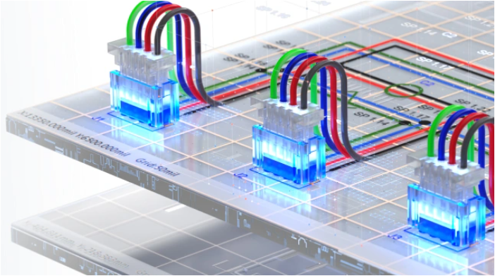
Optimize Your Multiboard PCB System with Intelligent Design and Manufacturing Solutions
Optimizing multiboard PCB systems demands visibility across logical, physical, and manufacturing domains. This article outlines how Altium’s environment lets engineers establish system‑level schematics, 3D spatial validation, harness documentation, and synchronized outputs to streamline design and production.

Blog
•
Why Mechanical Engineers Struggle With ECAD Collaboration (And How to Fix It)
If you’ve ever been frustrated by clunky PCB-to-mechanical workflows, you’re not alone. Learn why collaboration between mechanical and electrical engineers is harder than it should be and what’s behind the struggle.


Blog
•
Digital Thread for Electronics: Synchronizing PCB, Multi-Board, and Harness Design
Eliminate costly mismatches and assembly delays. This whitepaper shows you how to apply a unified digital thread across PCB, multi-board, and harness workflows - bridging ECAD/MCAD silos, ensuring connector accuracy, mechanical fit, and real-time collaboration for flawless system design.


Blog
•
Building a Model Context Protocol Server for Arduinos
This guide walks you through creating an MCP server that turns AI interactions with Arduino into a predictable, automated process handling tasks like board listing, compilation, and serial communication via a fast, menu‑driven interface. Skip the guesswork of prompt nudging and reduce the risk of unintended device issues.


Blog
•
Zero Voltage Switching in DC/DC Converters
Our brand-new article explains how zero-voltage switching improves performance in DC/DC converters through reduced losses, lower EMI, and smarter gate-drive control.

Blog
•
Getting Started with the GreenPAK Introduction Kit
Take your first steps into mixed-signal design with the Renesas GreenPAK Introduction Kit. Ari Mahpour shows how to design, simulate, and validate a clock divider project, making it easy for beginners to start experimenting with programmable mixed-signal devices.


Blog
•
Smarter Electronic Part Sourcing for Automotive Purchasing Professionals
Targeted at procurement professionals in the automotive industry, the article outlines the evolving pressures of sourcing components for electrified and connected vehicles. It highlights Octopart’s ecosystem as a unified tool that centralizes availability, compliance, pricing, and lifecycle intelligence to optimize sourcing efficiency.

Blog
•
Library Importer Improvements (former Library Migrator)
Importing file-based libraries from your local computer or network drive to your Altium 365 workspace can be done using the Library Importer. Altium’s Library Migrator was renamed Library Importer—the feature’s name was changed to conform more closely to the tool’s purpose. Not only is its name new, but our team has also made several user experience improvements. We have updated the documentation to reflect this change.

Blog
•
How to Select Copper Foil for High-Frequency PCB Design
The PCB materials industry has spent significant amounts of time developing materials that provide lowest possible signal loss for products with RF applications. For high speed and high frequency designs, losses will limit signal propagation distance and distort signals, and it will create an impedance deviation that can be seen in TDR measurements. In this article, we'll look at the balance between copper foil losses and other types of losses in a PCB, as well as some strategies that are commonly used to overcome roughness.

Blog
•
Altium Designer 22.8 Update
We are happy to announce that the Altium Designer 22.8 update is now available. Altium Designer 22.8 continues to focus on improving the user experience, as well as performance and stability of the software, based on feedback from our users. Check out the key new features in the What's New section on the left side of this window!

Blog
•
What is Hybrid Beamforming?
In this article, we’ll look at beamforming implementation in an advanced method combining analog and digital techniques, known as hybrid beamforming. This method blends both digital and analog techniques to create multiple beams and thus reach multiple users with varying intensities. In the case of an RF imaging system or a radar system, hybrid beamforming in a MIMO technique also allows tracking of multiple targets with adjustable resolution.

Blog
•
Why Most Via Impedance Calculators Are Inaccurate
The problem with every via impedance calculator that I have seen is simple: they are incomplete or totally wrong. The “incomplete” part refers to a lack of context; these calculators can roughly reproduce a well-known estimate from a legend like Howard Johnson in his Digital Design textbooks. However, these calculators never provide insight into what they are actually calculating, or where the calculated via impedance is accurate. Keep reading to see why these calculators get it so wrong, as well as the context surrounding via impedance.

Blog
•
Buck Converter Simulation in Altium Designer
When designing high power circuits (usually very high voltage and/or current), you’ll need to create a regulator from scratch and place it in your PCB layout. It's also the case that you may want to model a real component using discretes in a simulation in order to qualify the system's expected operating regime. As part of buck converter design, you can easily run a buck converter simulation directly in Altium Designer’s schematic editor. Here’s how you can access these features in the newest version of Altium Designer.

Blog
•
Overview of the PCIe 6.0 Standard
Just as you get used to PCIe 5.0, they decide to release another standard! The newest iteration of PCIe is Gen6, or PCIe 6.0. PCIe 6.0 brings a doubling of channel bandwidth through introduction of PAM-4 as the signaling method in high-speed differential channels. This signaling method is a first for PCIe, and it’s an important enabler of the doubled data rate we see in the current standard. In this article, I’ll run over the important points in the standard and what PCB designers can expect when designing these channels.

Blog
•
SPI vs. I2C: How to Choose the Best Protocol for Your Memory Chips
One of the common implementations of SPI and I2C in a PCB layout is as a protocol for reading and writing to an external Flash memory. Flash chips are a very common component in embedded systems and can offer high capacities of non-volatile memory up to Gb values. When choosing a memory chip, you'll want to match the application requirements and functionality with the bus speed you need for read and write operations in your memory chip. There is also the matter of the type of Flash memory you'll need to access (NOR vs. NAND).

Blog
•
Is There an SPI Trace Impedance Requirement?
There is no SPI trace impedance requirement? The reality is that SPI lines only start to need impedance control when the length of the interconnect becomes very long. And because there is no specific impedance requirement in the bus, you have some freedom in channel design and termination. So what exactly qualifies as “very long” and when is some termination method needed? We’ll break it down in this article.

Blog
•
The Skin Effect, Current Density, and the Electromagnetic Field
During this year's AltiumLive CONNECT event, I recall receiving an interesting question about the skin effect and the distribution of current due to the presence of ground in coplanar transmission lines. In this article, we'll look at the electric field around a transmission line carrying a signal, and how this might be impacted by the skin effect.

Blog
•
What You Need for PCB Packaging and Shipping
When you get your PCBA back from an assembler, you’ll notice the packaging materials used to pack and ship the PCBA. Those materials are specific to electronics, and if you build products on behalf of clients, it’s important to know the packaging materials used for packing and shipping electronics. In this article I’ll show the main set of materials and equipment used to package electronics assemblies.

Blog
•
How to Make PCB Gerber Files in Altium Designer Step-by-Step
Once you've got your PCB layout finished and you're ready to start preparing for manufacturing, one of the critical steps is to create PCB Gerber files. When you're ready to create your Gerber files, you need the right set of CAM processor tools that can take data from your PCB layout. In this article, we'll guide you through this process of how to make PCB Gerber files and show some example tasks you might need to perform to generate them.

Blog
•
Should You Place Teardrops on Differential Pairs?
One of the major factors impacting reliability of a PCBA is the use of teardrops on traces in the PCB. Like many aspects of reliability, the considerations also span into the signal integrity domain, particularly as more high-reliability products require greater data handling capabilities and run at higher speeds. In this article, I’ll break down the issues present in teardrop usage on differential pairs and how these may affect impedance.

Blog
•
The High-Reliability PCBA Design and Test Challenge
High-reliability electronics must go through multiple rounds of testing and qualification to ensure they can withstand their intended operating environment. Designing to performance standards, whether the baseline IPC standards or more stringent industry standards, is the first step in ensuring a reliable circuit board. In this e-book, readers will gain a thorough look into PCB testing and analysis, starting from basic tests performed on bare boards and completed assemblies.

Blog
•
AC Coupling Capacitors in PCIe Routing
Coupling capacitors find plenty of uses in analog applications and on differential protocols, acting essentially as high pass filters that remove DC bias carried seen on a signal. In the case of PCIe, there are a few reasons to place AC coupling capacitors on differential pairs beyond the fact that AC coupling capacitors are listed in the standard. In this article, we’ll look briefly at where to place coupling capacitors on PCIe links, as well as the reasons these are placed on PCIe links.

Blog
•
Altium Designer 22.7 Update
We are happy to announce that the Altium Designer 22.7 update is now available. Altium Designer 22.7 continues to focus on improving the user experience, as well as performance and stability of the software, based on feedback from our users. Check out the key new features in the What's New section on the left side of this window!


On-Demand Webinar
•
Jun 12, 2025
Proactive Lifecycle Management: Preventing Obsolescence Before It Hits


On-Demand Webinar
•
Apr 23, 2025
Collaborative Design Review: Ensuring Quality from Schematics to Supply Chain

On-Demand Webinar
•
Apr 22, 2025
From Prototype to Production: Optimizing BOM Costs Without Compromising Quality with Part Analytics


On-Demand Webinar
•
Apr 9, 2025
Component Selection in Altium Designer: Making Data-Driven Decisions with Data Integrations

On-Demand Webinar
•
Mar 25, 2025
Unlocking the full potential of your design team with Altium's enterprise solution

On-Demand Webinar
•
Jan 24, 2024
Discover How Altium Designer 24 Revolutionizes Team Dynamics in PCB Design