News & Updates

Blog
•
Everything You Need to Know About Stitching Vias
Stitching vias are something you often see spread around the surface layer of a PCB, but what are they? and should you be using them? In this guide, we'll go over some of the standard uses of stitching vias and when they should be used in a PCB.


Blog
•
PCB Stackup Basics
In comparison to the build-up of a PCB, the stackup is more concerned with the electrical type of each layer, that is are we working with signals, power, or ground. Continue reading to learn how you can optimize your layer stack.


Blog
•
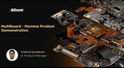
Multi-board and Harness Design Capability in Altium Designer 23
Altium’s VP of marketing Lawrence Romine discusses the multi-board and harness design capabilities coming in Altium Designer 23.


Blog
•
Controlled ESR Capacitors: Should You Use Them for Power Integrity?
Controlled ESR capacitors are important for power integrity in your design as they can help smooth out the PDN impedance spectrum in your high speed PCB.


Blog
•
How Does the Package PDN Impact Power Integrity?
Whenever we say something to the effect of “components can’t work without a correctly designed PCB,” we only have to look at component packaging for evidence. It is true that component packages come with parasitics that affect signal integrity, but there is one area that we don’t often look at in terms of component packaging: power integrity.


Blog
•
Designing Custom Hardware with Microcontrollers
In this article, we’ll look at all that is required to start creating your own custom microcontroller-based hardware designs. You’ll see that there actually isn’t too much to this, as microcontroller manufacturers over the years have tried to make the learning curve less steep and their devices more, and more accessible. This is both from an electrical point of view but also – equally importantly – from a programming point of view.


Blog
•
Guide to Low-Dk PCB Materials
If you’ve taken time to learn about PCB material options and layer constructions, you have probably seen the wide range of materials that are available on the market. Materials companies produce laminates with varying Dk values, Tg values, weave styles, CTI values, and mechanical properties to target various applications in the electronics industry.

On-Demand Webinar
•
Learn to Collaborate Like a Pro with Altium Designer 23
Get ready to speed up your design process with new Altium Designer collaboration capabilities. Designing a PCB is a team effort. Engineers must work with customers, manufacturers, and other stakeholders to get the best results. You need help to bring your design to life, even if you're a one-person team.

Blog
•
Designing for V2X Communication: Wireless Protocols and Standards
If you’re waiting for truly connected cars on a grand scale, there is still a massive amount of work to be done, both on the hardware and software sides. Connected cars can only become a widespread reality once the automotive industry and telecom carriers can decide which protocol will work best for vehicle-to-everything (V2X) communication. PCB designers will then need to step in to create these systems and fit them into a vehicular environment.

Blog
•
Image Processing Embedded Systems with Modular Hardware
With advances in industrial automation, automotive technology, remote sensing, and much more, image processing is taking center stage in many embedded systems. Image processing with older video systems was difficult or impossible due to the low quality of many imaging systems with perpetual uptime. Newer systems provide video with higher frame rates and higher resolution images, but these systems still needed to connect directly to a computer in order to enable any useful image processing applications.

Blog
•
Any Angle Routing: When Should You Use It?
EDA tools have come a long way since the advent of personal computing. Now advanced routing features like auto-routers, interactive routing, length tuning, and pin-swapping are helping designers stay productive, especially as device and trace densities increase. Routing is normally restricted to 45-degree or right-angle turns with typical layout and routing tools, but more advanced PCB design software allows users to route at any angle they like. So which routing style should you use, and what are the advantages of any angle routing?

Blog
•
Hardware-in-the-Loop Testing: An Introduction
If you do a search for “Hardware-in-the-Loop” testing, you will frequently find examples of complex, real-time systems. Article from National Instruments, for example, gives a nice explanation and background on what hardware-in-the-loop (HIL) is, and provides an example of testing electronic control units within an automobile. In this article, we will be focusing on a smaller, more bite-sized version of HIL testing concepts.

Blog
•
Near-field vs. Far-field EMI: What's Causing Noise Problems in My PCB?
If you’re an antenna designer, then you’re likely familiar with all aspects of near-field vs. far-field radiation. Given the litany of radiated EMI problems that cause noise within and outside of an electronic device, one might suddenly realize their new product is acting like a strong antenna. To understand how EMI affects your circuits, it helps to understand exactly how near-field vs. far-field radiation from your PCB affects your ability to pass EMC checks and affects your circuits.

Blog
•
Increasing PCB Prototype Iteration Speed in the Cloud
How often have you started down the PCB development process and been bogged down by time-consuming administrative tasks? Once you get ready for production, working through a design review and correcting any DFM problems takes its own share of time. With hastening product development timelines and shorter product life cycles comes the pressure to increase PCB prototype iteration speed without sacrificing cost or quality. So how can PCB design teams keep their development schedules on track without sacrificing quality or risking a failed prototyping run?

Blog
•
Why you should be using Concord Pro?
A journey of a thousand miles begins with a single step, or so the aphorism goes. I think it’s worth noting that the first step is the most difficult to take. Analysis Paralysis is especially true when dealing with a new software package, including the recent release of Concord Pro. The recent version has brought with it a deluge of interest and enthusiasm in such a phenomenal tool. But I must say, Altium hit this one out of the park.

Blog
•
What Types of EMI Filters are Best for Passing EMC Certification?
When you need to pass EMC certification and your new product is being crippled by a mysterious source of EMI, you’ll probably start considering a complete product redesign. Your stackup, trace geometry, and component arrangement are good places to start, but there might be more you can do to suppress specific sources of EMI. There are many different types of EMI filters that you can easily place in your design, and that will help suppress EMI in a variety of frequency ranges.

Blog
•
An Overview Of PCB Outer Layer Processing
Previously, I described the PCB fabrication operations relative to inner layer processing, lamination, drilling, and plating. The last step in the process is outer layer processing which is described below. Once the desired plated copper thickness of a PCB has been achieved, it’s necessary to etch away the copper between the features in order to define the outer layer pattern.

Blog
•
How Do Pads and Vias Impact Total Capacitor Parasitic Inductance?
There are many factors at play in determining the impact of inductance on high-frequency power distribution systems. Two topic areas, inductance of the decoupling capacitor and inductance of the power planes, were addressed in earlier articles. This article will focus on the inductance of the capacitor footprint and via inductance from the capacitor footprint back to the PCB power planes.

Blog
•
Analyzing Crosstalk on FIFO and DDR4 Parallel Bus Interfaces
High-speed buses, whether single-ended or differential, can experience any number of signal integrity problems. A primary problem created by propagating signals is crosstalk, where a signal superimposes itself on a nearby trace. The industry-standard PCB design tools in Altium Designer® already include a post-layout simulator for examining crosstalk. Still, you can speed up crosstalk analysis in parallel buses when you use a powerful field solver.

Blog
•
Amplifier Stability at High Frequencies and Stray Capacitance
Any time-dependent physical system with feedback and gain has conditions under which the system will reach stable behavior. Amplifier stability extends these concepts to amplifiers, where the system output can grow to an undesired saturated state due to unintended feedback. If you use the right design and simulation tools, you can easily account for potential instability in your circuit models before you create your layout.

Blog
•
Working with Design Variants
The concept of design variants entails taking a single PCB design, and then on the assembly side, modifying specific components used in the design. Either by not installing, not installing, or choosing alternate components as replacements on a specific assembly to ultimately create different end products. In that way, you could support multiple product lines. This article describes the approach to working with variants.

Blog
•
Setting Up Concord Pro Revisions and Lifecycle
Before anything else, some advice. The revisions and lifecycle are an area that takes some planning. It used to be that Concord Pro was primarily for components, but now it has gone far beyond that. With the ability to store and manage many other items, including your various templates, projects, even PDF documents, not everything will have the same revision scheme. Concord Pro is so powerful that it can handle any revision scheme you’d want to set up.

Blog
•
How to Successfully Design a BGA
Whether the board will be placed in a high pressure vessel or underwater, your design will need to withstand pressure to avoid failure. On the enclosure side, your vessel should be rated up to a certain pressure and may require frequent cycling to prevent implosion. On the electronics side, component selection and layout (especially at high voltage) become critical to preventing failure and ensuring reliability.

Blog
•
Altium Designer 20.2 Update 1 is now available
The first update of Altium Designer 20.2 and Altium NEXUS Client 3.2 is now available. You can update through the Altium Designer update system ("Extensions and Updates") or download fresh builds from the Downloads section of the Altium website. Click on "Read More" to see a list of all changes in this update.

Blog
•
How Copper Foil Roughness Affects Your Signals and Impedance
The history of engineering, both electrical and mechanical, is littered with approximations that have fallen by the wayside. These approximations worked well for a time and helped advance technology significantly over the decades. However, any model has limits on its applicability, and the typical RLCG transmission line model and frequency-independent impedance equations are no different. Copper foil roughness modeling and related transmission line impedance simulations are just one of many areas in which standard models cannot correctly treat signal behavior.


Your search returns no results.