News & Updates

Blog
•
Baxandall Volume Control for Audio
The Baxandall volume control is an especially useful, flexible, and simple-to-implement circuit for numerous audio designs. In this article, we will demonstrate how to design this type of equipment.



Blog
•
Common Flex Design Mistakes and How to Fix Them
Designing flexible circuits involves managing numerous factors. Discover how to prevent mistakes in this process and how to rectify them post-implementation.


Blog
•
How Much PCB Mask Expansion is Too Much?
In this article you will learn about finding the right balance between PCB mask expansion and potential problems.


Blog
•
RF Power Amplifier Module PCB Design
RF power amplifiers can be found in many wireless products, often integrated into chipsets or modems. However, in certain specialized systems, you might require higher power output at a specific frequency. This necessitates a discrete amplifier circuit to deliver that power. In this article, we present an example project for a power amplifier that you can incorporate into your RF project.


Blog
•
Avoid GIGO in Your PCB Simulation Tools
Simulation tools are extremely useful for understanding electromagnetic behavior in a design. Learn more about how to avoid obtaining inaccurate results during your PCB simulation process.


Blog
•
Choosing a Converter or Regulator For Your Power Supply Design
When designing the power supply for your device, there are lots of different options. In this article, we will take a brief tour of the main choices in DC power supply design.


Blog
•
The Benefits of Ultra HDI
Learn more about the combination of using both flexible materials and ultra-HDI feature sizes in this article.


Blog
•
Understanding Power Supply Current Handling Issues: Causes and Solutions
Troubleshooting power supply current handling issues is crucial to achieving optimal performance of your electronic devices. In this article, we will explore the common reasons why a power supply fails to handle the defined output current and provide practical solutions to solving these issues.

Blog
•
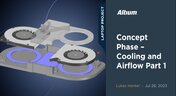
Concept Phase – Cooling and Airflow Part 1
Next step in our open-source laptop project is to explain how to design cooling and airflow. In this article, we can show you the first part of this process, such as airflow concept, fan measurement and clearance.


Blog
•
Create Connections with Harness Design
Many modern electronics have multiple boards, and connecting those different boards and systems together are harnesses. Learn more about how Altium Designer can help you create harnesses for your own multi-board designs here.

Blog
•
Avoid Costly Interconnect Errors: Essential Multiboard PCB Layout Strategies for Reliable Designs
Complex multiboard designs demand more than just connecting boards together. They require every interface to work flawlessly under real-world conditions. Discover how better pin assignments, return paths, and mechanical planning can dramatically improve reliability and reduce rework.

Blog
•
BOM Cost Optimization During Schematic Capture
Engineering and sourcing teams work best when BOM decisions happen with live market data in view. This article explains how integrated cost and availability insights help teams collaborate earlier and avoid redesigns driven by supply chain issues.

Blog
•
Why ECAD–MCAD Collaboration Is Essential to Design for Manufacturability (DFM)
Poor ECAD-MCAD coordination often leads to enclosure conflicts, connector misalignment, and costly redesigns. This article shows how integrated collaboration helps teams catch manufacturability issues earlier and keep projects moving smoothly.
Blog
•
Registration Tolerance Is Now a Design Constraint, Not a Fab Problem
Ultra HDI is changing the rules of PCB design and registration tolerance is now part of the design conversation from day one. Discover how smarter spacing, stackup planning, and collaboration with fabricators can dramatically improve manufacturability and reliability.

Blog
•
How to Use a Multicad Viewer for Seamless Collaboration
Because ECAD formats are typically incompatible, teams often struggle with versioning, conversions, and fragmented review processes. This article breaks down how multi-CAD viewers provide a unified, read-only environment that supports structured design reviews, comments, and task assignment across disciplines.

Blog
•
Best Online ECAD File Viewers for Engineers and PCB Designers
Sharing PCB designs doesn’t have to be complicated. Check out the best online ECAD viewers that let anyone view and collaborate on designs right from a browser.

Blog
•
Rigid-Flex PCBs in Consumer Electronics
Rigid-flex PCBs help modern devices get smaller, lighter, and more compact by eliminating connectors and fitting into tight 3D spaces. This article explains how to design them properly to avoid common reliability issues.

Blog
•
From Design to First Assembly: Complete Your BOM & Plan Your Build
This webinar walks through the complete post-release workflow, from generating a managed BOM to sourcing components and assembling the first prototype. It demonstrates how integrated tools streamline data enrichment, supplier selection, and guided assembly to reduce delays and errors.

Blog
•
The Future of BOM Management: Trends and Innovations
BOM management is no longer just a checklist. It’s becoming a real-time engine for smarter decisions! Discover how AI, automation, and connected systems are transforming BOMs into powerful tools for navigating supply chain uncertainty.

Blog
•
How to Use a Multicad Viewer for Seamless Collaboration
Working across different ECAD tools can make design reviews messy and inefficient. This article shows how a multi-CAD viewer simplifies collaboration by letting teams view, comment, and manage designs in one place.
NEW

Blog
•
Breaking the Multiboard Bottleneck: How Unified Design Solves ECAD–MCAD Disconnects
This article examines how fragmented ECAD-MCAD workflows create costly misalignments, late-stage conflicts, and inefficiencies in multiboard system design. It shows how unified, collaborative platforms enable real-time synchronization, digital twins, and cross-domain visibility to eliminate rework and streamline development.

Blog
•
Altium Designer vs. Flux For Professional PCB Projects
Choosing the right PCB tool can define your entire design workflow. Discover how Altium Designer empowers professional product development, while Flux.ai keeps things simple for fast experimentation.

Blog
•
Rigid-Flex Stackups: Where Good Designs Go Wrong Before Layout Even Starts
Rigid-flex stackups are more complex than they seem and getting them wrong early can lead to costly failures later. This article shows how smart decisions around materials, transitions, and layer structure help ensure a reliable design.

Blog
•
From Complexity to Clarity: Smart Design Reviews for Agile Engineering Teams
Understand how structured design reviews within Altium Agile Teams enhance visibility, traceability, and cross-team collaboration. This webinar highlights methods to detect issues early and optimize your development workflow.

Blog
•
Building a Local-LLM Datasheet Extractor for IC Driver Development
Parsing long datasheets manually slows down embedded development and introduces errors. This article shows how to use a local LLM pipeline to convert datasheets into structured data that speeds up driver creation.

Blog
•
Types of Simulation Tools For PCBs
PCB simulation isn’t one-size-fits-all and that’s where it gets interesting! Discover the wide range of tools available, from quick circuit checks to advanced multiphysics simulations, and how they help you design with confidence.


Your search returns no results.


