News & Updates

Blog
•
Rigid-Flex PCBs in Consumer Electronics
Rigid-flex PCBs help modern devices get smaller, lighter, and more compact by eliminating connectors and fitting into tight 3D spaces. This article explains how to design them properly to avoid common reliability issues.

Blog
•
From Design to First Assembly: Complete Your BOM & Plan Your Build
This webinar walks through the complete post-release workflow, from generating a managed BOM to sourcing components and assembling the first prototype. It demonstrates how integrated tools streamline data enrichment, supplier selection, and guided assembly to reduce delays and errors.

Blog
•
The Future of BOM Management: Trends and Innovations
BOM management is no longer just a checklist. It’s becoming a real-time engine for smarter decisions! Discover how AI, automation, and connected systems are transforming BOMs into powerful tools for navigating supply chain uncertainty.

Blog
•
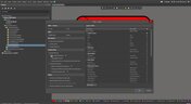
How to Use a Multicad Viewer for Seamless Collaboration
Working across different ECAD tools can make design reviews messy and inefficient. This article shows how a multi-CAD viewer simplifies collaboration by letting teams view, comment, and manage designs in one place.

NEW

Blog
•
Breaking the Multiboard Bottleneck: How Unified Design Solves ECAD–MCAD Disconnects
This article examines how fragmented ECAD-MCAD workflows create costly misalignments, late-stage conflicts, and inefficiencies in multiboard system design. It shows how unified, collaborative platforms enable real-time synchronization, digital twins, and cross-domain visibility to eliminate rework and streamline development.

Blog
•
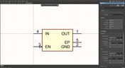
Altium Designer vs. Flux For Professional PCB Projects
Choosing the right PCB tool can define your entire design workflow. Discover how Altium Designer empowers professional product development, while Flux.ai keeps things simple for fast experimentation.
Blog
•
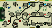
Rigid-Flex Stackups: Where Good Designs Go Wrong Before Layout Even Starts
Rigid-flex stackups are more complex than they seem and getting them wrong early can lead to costly failures later. This article shows how smart decisions around materials, transitions, and layer structure help ensure a reliable design.


Blog
•
From Complexity to Clarity: Smart Design Reviews for Agile Engineering Teams
Understand how structured design reviews within Altium Agile Teams enhance visibility, traceability, and cross-team collaboration. This webinar highlights methods to detect issues early and optimize your development workflow.

Blog
•
Building a Local-LLM Datasheet Extractor for IC Driver Development
Parsing long datasheets manually slows down embedded development and introduces errors. This article shows how to use a local LLM pipeline to convert datasheets into structured data that speeds up driver creation.


Blog
•
Types of Simulation Tools For PCBs
PCB simulation isn’t one-size-fits-all and that’s where it gets interesting! Discover the wide range of tools available, from quick circuit checks to advanced multiphysics simulations, and how they help you design with confidence.

Blog
•
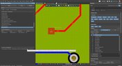
Wiring the Future: The Shift to Unified Electromechanical Design
This article explores the shift from PCB-centric design to complex, system-level development where wiring and harnesses play a critical role in product performance. It highlights how unified electromechanical workflows and bi-directional ECAD–MCAD integration improve accuracy, reduce delays, and ensure reliable, production-ready designs.

Blog
•
Best Tools For PCB DFM Checks
Want to catch manufacturability issues before they turn into expensive delays? Discover the essential DFM tools from real-time checks to post-layout analysis that help you get your PCB right the first time.
Blog
•
MCAD CoDesigner 2.9.0 is Out
Altium has released version 2.9.0 of the MCAD CoDesigner. This version has the option to exclude small components when transferring from ECAD to MCAD. The arc behavior was improved, and the support for splines in board shape and cutouts was added. With this release, you can now select a specific SOLIDWORKS configuration of a part to use on the board and view the improvements made for Siemens NX.

Blog
•
Support for Rigid-Flex in Altium Designer
Altium Designer's world-class PCB design features help users quickly get started with new rigid-flex designs and prepare them for manufacturing. Rigid-flex in Altium Designer starts with designing a manufacturable PCB layer stack complete with via transitions and any calculated impedance requirements. Keep reading to see how Altium Designer supports your flex and rigid-flex designs.
Blog
•
2+N+2 PCB Stackup Design for HDI Boards
Like any other advanced PCB, success in HDI design comes from designing the right stackup. One common HDI stackup used to support routing into moderate pin count, high-density BGA components is the 2+N+2 PCB layer stack for HDI boards. We’ll explore this stackup more in this article, as well as how it is related to other advanced stackups used in HDI PCBs.
Blog
•
PDF in Altium 365 Web Viewer
Altium 365 Web Viewer now includes a built-in PDF viewer that allows you to view PDF files in releases without an external PDF viewer application. Keep reading to learn about new key features that make your work easier

Blog
•
Flex and Rigid-Flex PCB Applications
There are two basic reasons for designing a flex circuit into your product: to build a compact and efficiently assembled device, or to make the circuit dynamically integrated with the mechanical function of the product. You may, of course, lean on both of these reasons for justifying the use of flex circuits. On this note, let’s look at some rigid-flex PCB applications and design examples to see the issues that spring to mind when designing flex circuits
Blog
•
Granular Sharing — Role and Group Management
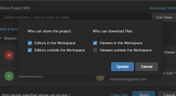
With Altium 365, you can grant permission to teams or users based on the specific needs of a project. We have expanded Altium 365’s file-sharing setting, giving you more granular control over who can download source files and reshare projects with others

Blog
•
Design Rule Checking in the PCB Design Workflow
Any time you design a PCB, and you want to turn it into a real product, you will have to make sure the design obeys the constraints within the standard PCB manufacturing process. This imposes multiple rules on any design, and ECAD software will enforce design rules as you create the board to ensure you obey these important constraints. Make sure you enforce the right design rules at the beginning of the PCB design workflow

Blog
•
Best Practices for High-Frequency PCB Material Selection
High frequency PCB design can seem esoteric, and I've heard many an engineer describe it as "black magic"! The subject is also a bit confusing, especially once someone asks which frequencies could be reasonably considered "high". Before you do anything inside the layout for a high-speed or RF PCB, you will need to pay attention to the materials being used in the board. If you're unsure which high frequency PCB materials you should use, then keep reading to learn more.

Blog
•
PCB Noise Reduction: Do You Need Isolation, Shielding, or Filters?
Of all the noise and operational challenges designers face in their PCBs, there is one overarching problem that is arguably most popular: electronic noise. It could originate as an SI/PI problem, it could possibly arise from some external source, or it could be good old-fashioned crosstalk! These tend to fall into three categories: adding shielding, doing something to create isolation, or placing filters. Let's look at all of these as they tend to be the default solution set when confronted with many noise problems.
Blog
•
What’s New in Altium 365: Version Control for Hardware, Layer Stackup in Web Viewer, and SOC 2 Type 1 Certification
In February, we hit a new record in the number of users on the platform. The Altium 365 user community is now 20,000 strong! You can now migrate from an external version control system to Altium 365 preserving the history of commits. We also received the SOC 2 Type 1 certification from KPMG, made layer stack available in the web viewer, and added the brand new capability to track tasks in the context of your design project. Keep reading to learn more!

Blog
•
Introducing Spectra's Electronic Design to Delivery Index
Get a cohesive view of supply chain market conditions, stay on top of trends, and avoid disruption with this free, monthly report from Spectra.

Blog
•
Support for Rigid-Flex in Altium Designer
Rigid-flex in Altium Designer starts with designing a manufacturable PCB layer stack complete with via transitions and any calculated impedance requirements. Flex sections also need to be placed in the layer stack before moving into the PCB layout. Once inside the PCB editor, bending lines can be clearly defined in the PCB layout, and these can be visualized in Altium Designer's 3D PCB design tools. Keep reading to see how Altium Designer supports your flex and rigid-flex designs.
Blog
•
Communicating PCB Layer Stackup Needs to Manufacturers
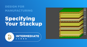
In the business of PCB design, communicating needs to manufacturers and vendors is a top priority. The context of our requests is sometimes lost either by not providing the correct information, not listing enough information, or not giving any information. Although the experienced PCB designer can take steps to specify everything they want to see in their PCB stackup, eventaully the manufacturer will handle that decision in an effort to balance available materials with processing capabilities and yield.

Blog
•
Risk Vs. Reward
During the recent IPC APEX expo, there was a lot of discussion about SAP, or semi-additive PCB processes. As with any new technology adoption there were people that are excited to jump right in and start designing with much finer feature sizes and work through the inevitable changes to the traditional thought process. Others are in a "let’s wait and see" mode and of course there are a few skeptics there as well, so keep reading to learn more.

Blog
•
Parasitic Extraction with an Electromagnetic Solver in PCB Routing
Parasitic extraction: the integrated circuit design community must grapple with this task on a daily basis, especially once gate features are reduced below ~350 nm and chips run at high switching speeds. The PCB community also has to deal with this idea in order to better design power delivery networks, interconnects with precise impedance, and properly quantify crosstalk and coupling mechanisms.
Blog
•
Ebook: PDN Simulation and Analysis Guide
Most designers don’t realize they need to worry about power integrity until they have a power integrity problem. Other designers might build boards that can’t handle the demands of modern digital and high frequency components, and they may not realize the problems that lurk in their power delivery network (PDN). Although the basic concepts involved in designing for power integrity are well-known, myths about power integrity abound, and designers need tools to help them evaluate and qualify power integrity in a PDN.















Your search returns no results.


