Welcome, Guest

Sign in to learn, create, and do more with the product you love.

News & Updates

Filters:
Tag
Embedded thumbnail for Creating a Schematic Symbol - Placing Designators and Comments
How to create a Schematic Symbol
Creating a Schematic Symbol - Placing Designators and Comments

Placing your designator or comments can be done automatically, but that doesn’t mean they’re visible. We’ll walk you through how to make them visible and position them correctly no matter what orientation your symbol is with automatic positioning.

Embedded thumbnail for Creating a Schematic Symbol: Adding Additional Parts
How to create a Schematic Symbol
Creating a Schematic Symbol: Adding Additional Parts

Altium Designer makes it easy to add additional parts to your schematic library. We’ll show you how through copying and configuring your new components through the Pin Editor and the properties panel.

Designing the Next-Generation Electronics
Blog
A-SAP™ – What do you need to know?

The continued miniaturization of both packaging and component size in next-generation electronics is becoming harder and harder to work around and presents a significant challenge for both PCB designers and PCB fabricators. To effectively navigate the constraints of the traditional subtractive-etch PCB fabrication processes, PCB designs require advanced PCB fabrication capabilities while pushing the limits of finer feature size, higher layer counts, multiple levels of stacked micro vias and increased lamination cycles.

Embedded thumbnail for Component Placement Control Using Rooms
How to work with Rooms
Component Placement Control Using Rooms

Rooms give you more control over how and where your components are placed in your PCB. We’ll show you how to use room properties to limit what is allowed in and out of a room using the room definition and custom queries.

Pin-package and Via Delay Values
Blog
Pin-Package Delay and Via Delay in High Speed Length Tuning

Take a look at the inside of some integrated circuit packages, and you’ll find a number of wires bonded to the semiconductor die and the pads at the edge of the component's package. As a signal traverses makes its way along an interconnect and into a destination circuit, signals need to travel across these bond wires and pads before they are interpreted as a logic state. As you look around the edge of an IC, these bond wires can have different lengths, and they incur different levels of delay and contribute to total jitter.

Embedded thumbnail for How to work with Differential Pair Classes?
How to Work with Differential Pairs
How to work with Differential Pair Classes?

Modern boards can contain a large number of differential pairs. For convenience, they are combined into differential pairs classes. In this video, we'll walk you through how to create and apply a differential pair class. 

Embedded thumbnail for Adding Rooms from the Schematic
How to work with Rooms
Adding Rooms from the Schematic

Rooms can be added directly from the schematic sheet. From the schematic sheet they are pushed to the PCB. Here we'll look at the rooms and component classes generated by default in the schematic, how to add and configure rooms manually, and how to push them to the PCB.

6-Layer PCB Design
Blog
6-Layer PCB Design Guidelines

Once you’ve run out of room on your 4-layer PCB, it’s time to graduate to a 6-layer board. The additional layer can give you room for more signals, an additional plane pair, or a mix of conductors. How you use these extra layers is less important than how you arrange them in the PCB stackup, as well as how you route on a 6-layer PCB. If you’ve never used a 6-layer board before, or you’ve had EMI troubles with this stackup that are difficult to solve, keep reading to see some 6-layer PCB design guidelines and best practices.

Component Management
On-Demand Webinar
Help Ensure The Best Designs With Component Management

There are many aspects to designing a PCB. One of the larger aspects has to do with managing your components. We all need components for our designs, but are those components in our library and designs up-to-date or even purchasable? These questions need to be answered before we can safely use them. If not, we could just be wasting our time designing with invalid components. Altium Designer® has several tools to help you manage the components in your libraries and designs.

Altium Designer Interface
Blog
Altium Designer 22.5 Update

We are happy to announce that the Altium Designer 22.5 update is now available. Altium Designer 22.5 continues to focus on improving the user experience, as well as performance and stability of the software, based on feedback from our users. Check out the key new features in the What's New section on the left side of this window!

Are Hybrid PCB Stackups Reliable?
Blog
How Reliable is Your Hybrid PCB Stackup?

PCB stackups often incorporate slightly dissimilar materials that could pose a reliability problem. Hybrid PCBs are one case where the PCB stackup will include different materials, typically a standard FR4 laminate and a PTFE laminate for RF PCBs. Designers who want to take the lead on material selection when designing their hybrid stackups should consider these factors that affect reliability. As with any PCB stackup, make sure you get your fabricator involved in the manufacturing process early to ensure reliability problems do not arise during production.

Embedded thumbnail for How to Draw a Board Outline Using Coordinates
How-To's
How to Draw a Board Outline Using Coordinates

In this video, we cover how to draw a curve by using coordinates. This can be very helpful when creating a board outline.

Embedded thumbnail for Creating a Schematic Symbol: Mapping out the Component
How to create a Schematic Symbol
Creating a Schematic Symbol: Mapping out the Component

When creating a schematic symbol, one of your first tasks will be creating a component symbol. We’ll show you how to map out a component in the Schematic Library Editor by creating and configuring the component, adding pins, and creating graphics.

Monte Carlo vs Sensitivity Analysis
Blog
Monte Carlo Simulation vs. Sensitivity Analysis: What’s the Difference?

In a previous article about circuit simulation and reliability, I looked at how Monte Carlo analysis is commonly used to evaluate circuits that are subject to random variations in component values. Sensitivity analysis is a bit different and it tells you how the operating characteristics of your circuit change in a specific direction. Compared to a Monte Carlo simulation, sensitivity analysis gives you a convenient way to predict exactly how the operating characteristics will change if you were to deliberately increase or decrease the value of a component.

Embedded thumbnail for How and When to Use Rooms
How to work with Rooms
How and When to Use Rooms

Rooms are an extremely valuable tool within the Altium Designer PCB environment, but how and when do you use rooms? If you need to control component placement and layout, assign a specific design rule to a group of items, or if you have repeated channels that need similar layouts in your multichannel design, rooms can make it much easier.

Simulation, Build and Test
Blog
Creating Continuous Integration Pipelines for FPGAs

Field Programmable Gate Arrays, or FPGAs, have become ubiquitous amongst high-speed, real-time digital systems. The speed at which FPGAs operate continues to increase at a dizzying pace but their adoption into Continuous Integration pipelines seems not to trail as closely. In this article we will review the concept of CI pipelines, their application to FPGAs, and look at examples on how to set this up.

Embedded thumbnail for MCAD CoDesigner Quick Start: Autodesk Fusion 360
Working with MCAD CoDesigner extension
MCAD CoDesigner Quick Start: Autodesk Fusion 360

MCAD CoDesigner is built to address the challenges of electronic product design by enabling seamless collaboration between your electrical and mechanical engineers. This video will show you how to start collaborate between Altium Designer and Autodesk Fusion 360. 

Embedded thumbnail for Component Placement Control for DFM
DFM and Fabrication Cost/Time Constraints
Component Placement Control for DFM

Component placement is a crucial part of making sure your design is manufacturable, so you need to be able to control placement. We’ll show you how, through rules and courtyard layers to maintain accessibility and manufacturability in your entire design through component placement control.

Collaborators Visualization
Blog
Soft Locks [Conflict Prevention] in Altium 365

Conflicts can occur when multiple people work on the same project simultaneously. The user might not realize that they are not looking at the latest version of the documentation, leading to problems later. To address this issue, Altium features an intuitive graphical user interface that allows you to examine conflicts quickly and carefully

Component Creation
On-Demand Webinar
Increase Productivity With Easy Component Creation

Component creation is a necessary evil when it comes to design, and it’s something we all need to do. But instead of spending hours creating your components and having them turn into a complete roadblock, let it be just a simple bump on the road. Altium Designer has several tools available to you in order to create the different aspects of a component, including the symbol, footprint, 3D model parametric data, supply chain information, and more

Tag
Blog
Types of Simulation Tools For PCBs

PCB simulation isn’t one-size-fits-all and that’s where it gets interesting! Discover the wide range of tools available, from quick circuit checks to advanced multiphysics simulations, and how they help you design with confidence.

Blog
Wiring the Future: The Shift to Unified Electromechanical Design

This article explores the shift from PCB-centric design to complex, system-level development where wiring and harnesses play a critical role in product performance. It highlights how unified electromechanical workflows and bi-directional ECAD–MCAD integration improve accuracy, reduce delays, and ensure reliable, production-ready designs.
Blog
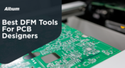
Best Tools For PCB DFM Checks

Want to catch manufacturability issues before they turn into expensive delays? Discover the essential DFM tools from real-time checks to post-layout analysis that help you get your PCB right the first time.

Blog
Eliminate Your Design Friction with Agile Teams

Design friction from scattered data and disconnected tools slows down PCB development and leads to rework. This webinar shows how Agile Teams streamlines collaboration, aligns domains, and helps teams deliver faster with fewer errors.

Blog
What is the Best Cloud PCB Design Software?

Not all cloud PCB tools are created equal, especially when design complexity increases. This article breaks down key differences between cloud-native and hybrid solutions, helping engineers choose the right approach for performance and scalability.

Blog
From Rework to Revenue: Digital PCB DFMA

This article explores how traditional, manual DFMA workflows lead to costly rework, delays, and poor collaboration across engineering teams. It shows how a connected, digital approach enables better data integrity, faster design cycles, and improved manufacturing outcomes.

Blog
How to Choose the Right Components for Your BOM

A strong BOM can make the difference between smooth production and costly delays. Discover a practical approach to choosing components that stay available, meet compliance requirements, and keep your project on schedule.

Blog
From Scattered Requirements to Confident Product Development

See how the Requirements Portal transforms disconnected requirements into a single, live source of truth that engineers can trust at every stage of a project! Real customer stories in the article prove it’s already helping teams cut down on rework and bring products to market faster.

Blog
What is the Best PCB Design Tool For Students?

Students need PCB software that’s intuitive, affordable, and useful for building real skills. This article compares the strengths and weaknesses of leading design tools, from hobbyist platforms to industry-standard software.

Blog
What Is Collaborative Engineering?

Collaborative engineering is all about breaking down silos so electrical, mechanical, and sourcing teams can work as one with shared data and real-time updates. This article shows how that approach helps you spot issues early, reduce rework, and get products out the door with fewer surprises.

Blog
Bend Reliability: How Trace Geometry and Materials Impact Flex Lifespan

Focused on durability under repeated mechanical stress, this piece details how routing strategy, copper thickness, adhesive systems, and bend radius selection determine flex lifespan. Engineers will find actionable recommendations for reducing strain concentration and improving long-term performance in high-cycle applications.

Blog
PCB Design Process: The EDA Design Approach

Dive into how a modern EDA workflow transforms PCB design by linking electrical, mechanical, and manufacturing requirements from idea to final release. With constraint‑driven integration, you can cut down on respins and bring better boards to market faster.

Blog
Getting Started for Mechanical Engineers

Explore our collection of MCAD Collaboration walkthroughs, where you’ll discover how to synchronize mechanical constraints and keepouts, maintain traceability with advanced history and revision control, and streamline electromechanical connectivity through harness synchronization. These topics and many more are covered in this article.

Blog
Are Your ECAD Tools Holding Back Engineers’ Productivity?

The article highlights that productivity issues often stem from tool limitations rather than engineer effort, especially as project complexity grows. ECAD tools that offer clear version control, cross-discipline integration, and workflow awareness are key to sustaining efficiency.

Tag
Embedded thumbnail for Edge Plating in RF Design
How-To's
Edge Plating in RF Design

PCB Edge Plating provides additional noise suppression and improves EMC. In this video we provide you some practical tips for creating metalized PCB edges in Altium Designer.

Embedded thumbnail for Custom Paste Mask and Solder Mask
Custom Pad Stack in Altium Designer
Custom Paste Mask and Solder Mask

Altium Designer allows you to freely customize paste and solder mask shapes, which allows you to adapt your design for non-standard component footprints.

Embedded thumbnail for Colpitts Oscillator
Simulation in Altium Designer
Colpitts Oscillator

Learn how to effectively fix errors in circuit simulation and other problem-solving techniques using a Colpitts Oscillator design as an example. 

Embedded thumbnail for Custom Thermal Reliefs for Pads
Custom Pad Stack in Altium Designer
Custom Thermal Reliefs for Pads

Altium Designer allows you to add, remove, and edit thermal relief spikes anywhere on a pad, regardless of its shape. Using these can improve soldering and prevent manufacturing problems like tombstoning.

Embedded thumbnail for Notch Filter
Simulation in Altium Designer
Notch Filter

Learn how to run an AC sweep analysis, execute a Monte Carlo simulation, and interpret the results using a notch filter as an example. 

Embedded thumbnail for Custom Pad Shapes
Custom Pad Stack in Altium Designer
Custom Pad Shapes

Modern components often contain pads with complex shapes. Altium Designer allows you to create custom pad shapes quickly and easily, and manage them like you would a standard pad.

Embedded thumbnail for Low-Pass Filter
Simulation in Altium Designer
Low-Pass Filter

Learn how to modify an op amp low-pass filter circuit for simulation. 

Embedded thumbnail for Design Reuse
How-To's
Design Reuse

If you need to shorten your time-to-market, reduce costs, and minimize errors in the design process. Then you need to make sure that you’re designing smarter, with design reuse blocks. Check out this demo to see how it works.

Embedded thumbnail for Flyback Converter
Simulation in Altium Designer
Flyback Converter

Learn how to use transient analysis on an example flyback converter and handle basic errors during the simulation preparation. 

Embedded thumbnail for Back Drilling in Altium Designer
How-To's
Back Drilling in Altium Designer

In this video, we will learn about Back Drilling technology, how to set up back drilling using the Layer Stack Manager, and how to set up the Stub Length sizes for back drilling by specifying applicable nets using the Design Rules Editor.

Embedded thumbnail for Distributed - Element Circuits in RF Design
How-To's
Distributed - Element Circuits in RF Design

The capacitance and inductance of Distributed-Element circuits are determined by the shape and location of different copper elements in the PCB layout, instead of being concentrated in one point in space. Learn how to work with these circuits in Altium Designer.

Embedded thumbnail for Collaborative Editing
How-To's
Collaborative Editing

Save time and minimize reworks while teaming up on a PCB design from anywhere in the world. Watch the video for a sneak preview of the new collaborative editing functionality.

Embedded thumbnail for Exporting Results
How To Work with Power Analyzer by Keysight
Exporting Results

After completing your simulation in Power Analyzer by Keysight, you will likely need to export some of the results for further analysis. In this video, we will show you how to prepare a report once the simulation is done.

Embedded thumbnail for Plane Connect - Direct in RF Design
How-To's
Plane Connect - Direct in RF Design

Designing high-frequency circuit boards requires a sharp eye toward maintaining signal integrity. Some signal connections are more prone to interruption than others. In this video, you can learn how Altium Designer's Polygon Connect Design Rule and the Thermal Relief option can help in the PCB design process.

Embedded thumbnail for Understanding and Correcting Violations
How To Work with Power Analyzer by Keysight
Understanding and Correcting Violations

When you finish the Power Analyzer by Keysight simulation process, you may find some design problems. In this video, we will learn how to understand and correct any violations that may arise on your board.

Embedded thumbnail for Routing Any Angle or Arc in RF Design
How-To's
Routing Any Angle or Arc in RF Design

High-frequency signals require special consideration when routing. Altium Designer allows you to add RF nets to a net class, then apply design rules. Learn how, as well as some other handy high-frequency routing tips, in this video.

Tag
Your search returns no results.