News & Updates

Blog
•
SAP (Semi-Additive PCB Process) – Top 5 Questions Regarding Stack Up
This Semi-Additive Process is an additional tool in the PCB fabricators' toolbox that enables them to provide feature sizes for trace width and spacing that are 25 microns, (1 mil) and below depending on the fabricators' imaging equipment. This provides much more flexibility to breakout out tight BGA areas and the ability to shrink overall circuit size and/ or reduce the number of circuit layers in the design. As the PCB design community embraces the benefits of this new printed circuit board fabrication technique, there are of course many questions to be answered.


Blog
•
Improving Supply Chain Success with BOM Management
It’s no secret that component shortages have become more frequent this year. In fact, countries around the world are losing billions in revenue due to supply issues. Having the right components on hand is more crucial than ever as availability, obsolescence, counterfeit products and environmental non-compliance risks continue to grow. Fortunately, many shortages can be avoided by introducing proactive supply chain practices.

Blog
•
What is the Impedance of Length-Tuning Structures?
Do length-tuning structures create an impedance discontinuity? The answer is an unequivocal “yes”, but it might not matter in your design depending on several factors. Applying a length-tuning structure is equivalent to changing the distance between the traces while meandering. Therefore, you will have a change in the odd-mode impedance of a single trace. The question then becomes: does this deviation in trace impedance in a length tuning structure matter?


Blog
•
A-SAP™ – What do you need to know?
The continued miniaturization of both packaging and component size in next-generation electronics is becoming harder and harder to work around and presents a significant challenge for both PCB designers and PCB fabricators. To effectively navigate the constraints of the traditional subtractive-etch PCB fabrication processes, PCB designs require advanced PCB fabrication capabilities while pushing the limits of finer feature size, higher layer counts, multiple levels of stacked micro vias and increased lamination cycles.


Blog
•
Pin-Package Delay and Via Delay in High Speed Length Tuning
Take a look at the inside of some integrated circuit packages, and you’ll find a number of wires bonded to the semiconductor die and the pads at the edge of the component's package. As a signal traverses makes its way along an interconnect and into a destination circuit, signals need to travel across these bond wires and pads before they are interpreted as a logic state. As you look around the edge of an IC, these bond wires can have different lengths, and they incur different levels of delay and contribute to total jitter.


Blog
•
6-Layer PCB Design Guidelines
Once you’ve run out of room on your 4-layer PCB, it’s time to graduate to a 6-layer board. The additional layer can give you room for more signals, an additional plane pair, or a mix of conductors. How you use these extra layers is less important than how you arrange them in the PCB stackup, as well as how you route on a 6-layer PCB. If you’ve never used a 6-layer board before, or you’ve had EMI troubles with this stackup that are difficult to solve, keep reading to see some 6-layer PCB design guidelines and best practices.
Blog
•
Altium Designer 22.5 Update
We are happy to announce that the Altium Designer 22.5 update is now available. Altium Designer 22.5 continues to focus on improving the user experience, as well as performance and stability of the software, based on feedback from our users. Check out the key new features in the What's New section on the left side of this window!

Blog
•
How Reliable is Your Hybrid PCB Stackup?
PCB stackups often incorporate slightly dissimilar materials that could pose a reliability problem. Hybrid PCBs are one case where the PCB stackup will include different materials, typically a standard FR4 laminate and a PTFE laminate for RF PCBs. Designers who want to take the lead on material selection when designing their hybrid stackups should consider these factors that affect reliability. As with any PCB stackup, make sure you get your fabricator involved in the manufacturing process early to ensure reliability problems do not arise during production.


Blog
•
Monte Carlo Simulation vs. Sensitivity Analysis: What’s the Difference?
In a previous article about circuit simulation and reliability, I looked at how Monte Carlo analysis is commonly used to evaluate circuits that are subject to random variations in component values. Sensitivity analysis is a bit different and it tells you how the operating characteristics of your circuit change in a specific direction. Compared to a Monte Carlo simulation, sensitivity analysis gives you a convenient way to predict exactly how the operating characteristics will change if you were to deliberately increase or decrease the value of a component.


Blog
•
Creating Continuous Integration Pipelines for FPGAs
Field Programmable Gate Arrays, or FPGAs, have become ubiquitous amongst high-speed, real-time digital systems. The speed at which FPGAs operate continues to increase at a dizzying pace but their adoption into Continuous Integration pipelines seems not to trail as closely. In this article we will review the concept of CI pipelines, their application to FPGAs, and look at examples on how to set this up.

Blog
•
How Much PCB Mask Expansion is Too Much?
In this article you will learn about finding the right balance between PCB mask expansion and potential problems.
Blog
•
RF Power Amplifier Module PCB Design
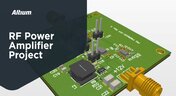
RF power amplifiers can be found in many wireless products, often integrated into chipsets or modems. However, in certain specialized systems, you might require higher power output at a specific frequency. This necessitates a discrete amplifier circuit to deliver that power. In this article, we present an example project for a power amplifier that you can incorporate into your RF project.

Blog
•
Avoid GIGO in Your PCB Simulation Tools
Simulation tools are extremely useful for understanding electromagnetic behavior in a design. Learn more about how to avoid obtaining inaccurate results during your PCB simulation process.

Blog
•
Choosing a Converter or Regulator For Your Power Supply Design
When designing the power supply for your device, there are lots of different options. In this article, we will take a brief tour of the main choices in DC power supply design.

Blog
•
The Benefits of Ultra HDI
Learn more about the combination of using both flexible materials and ultra-HDI feature sizes in this article.

Blog
•
Understanding Power Supply Current Handling Issues: Causes and Solutions
Troubleshooting power supply current handling issues is crucial to achieving optimal performance of your electronic devices. In this article, we will explore the common reasons why a power supply fails to handle the defined output current and provide practical solutions to solving these issues.
Blog
•
Concept Phase – Cooling and Airflow Part 1
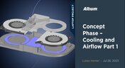
Next step in our open-source laptop project is to explain how to design cooling and airflow. In this article, we can show you the first part of this process, such as airflow concept, fan measurement and clearance.
Blog
•
Create Connections with Harness Design
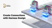
Many modern electronics have multiple boards, and connecting those different boards and systems together are harnesses. Learn more about how Altium Designer can help you create harnesses for your own multi-board designs here.
Blog
•
Do You Know How to Prevent Voltage Fluctuation?
We invite you to explore the causes of output voltage fluctuation. In this article we provide you insights on how to solve and prevent these issues.
Blog
•
How to Build Your Own Laser Range Finder
In this article we will show you how to create step by step a digital laser range finder for your own. Everything is based on Raspberry Pi board.
Blog
•
Nucleo Shields Multi-Board Design
Learn how easy it is to create multi-board projects. This practical project article covers the reasons for breaking larger boards into sub-assemblies and explores the various connection options available between sub-assembly boards.
Blog
•
Analog Solar Tracker Project
In this article you can learn about light sensors while building an analog solar panel tracking system. This open-source project covers multi-channel design, window comparators, driving motors, and photosensors.

Blog
•
Concept Phase – Initial CAD Design
We are continuing our journey through the open-source laptop project. This article explains an initialization of CAD design process from the early concept and brainstorming phase.
Blog
•
Expert Tips for Safely Powering Up Your New PCB for the First Time
In this blog we will show you the strategies to minimize the risk of damage to circuit boards during the initial power-up process.

Blog
•
High-Speed PCB Design Tips
Essential tips for high-speed PCB designs, and when you need to start being concerned about how and where you route your traces.
Blog
•
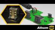
MIDs Make a Comeback as Vertical SMD Modules for Your PCB
If you've ever wanted to mount components vertically, but without the expense of a flex section this article is for you. You can use an MID in your PCB.


Your search returns no results.


