News & Updates
NEW

Blog
•
How Design Review Automation Saves Hours (and Headaches) Per Project
Design review automation helps teams spend less time managing feedback and more time improving the design. This article explores how centralized comments, structured checklists, action tracking, and approval workflows can make reviews faster, more consistent, and easier to close.

NEW

Blog
•
Comparing Flex and Rigid-Flex PCBs: When to Use What?
This article compares flex and rigid-flex PCBs across key design and manufacturing considerations, including cost, bend radius, impedance, and assembly complexity. It explains how choosing the right construction early can help reduce design risks and ensure better manufacturability.


Blog
•
The Security and Speed of Cloud-Based Electronics Design for Engineering Teams
Security shouldn't be the reason your engineering team slows down. This article explores how cloud-based design platforms can turn secure access, governance, and IP protection into an enabler of faster collaboration rather than another development bottleneck.

Blog
•
PCB Assembly Outputs
The right PCB assembly outputs turn a finished design into a buildable product. This article covers the essential manufacturing files and DFA considerations that help ensure assemblers have the information they need for accurate, reliable production.


Blog
•
Holistic Engineering Management in Electronic Design
This webinar explores how engineering leaders can gain greater visibility and control across complex electronic design workflows. Discover how connected processes and centralized design data help teams reduce risk, improve collaboration, and deliver projects on time.

Blog
•
PCB Design Variants: Managing Multiple PCBA Versions
Product variations often require different component populations, alternate parts, or configuration settings while keeping the underlying PCB design unchanged. This article explains how structured variant management keeps these differences organized and ensures each configuration has the correct BOM and manufacturing outputs.


Blog
•
8 Common DFM Problems PCB Design Rules Catch Before Fab
Preventing DFM problems starts before fabrication not during the fab review. This article covers eight common PCB manufacturing issues and the design rules that help engineers identify and resolve them early.


Blog
•
What is a Multi-CAD Environment? Advantages and Best Practices
Different CAD tools shouldn't mean disconnected teams. Learn how Multi-CAD workflows help engineers review designs, collaborate across disciplines, and catch mechanical or sourcing issues before they become costly redesigns.

Blog
•
Deliver Production-Ready Multiboard PCBs Faster with Manufacturing-Driven Design
This article explores how manufacturing-driven design can help teams validate multiboard products before they reach the factory. It highlights how early checks of interconnects, harnesses, mechanical fit, sourcing, and manufacturing data can reduce late-stage changes and accelerate production readiness.


Blog
•
Stop Chasing Signatures: How Automated Design Sign-offs Accelerate Release Cycles
Automated design sign-offs can eliminate much of the administrative friction surrounding hardware approvals. This article explores how in-context reviews, structured workflows, and automated traceability help teams accelerate release cycles while maintaining control.

Blog
•
What Target Impedance Should You Use in Your PDN?
A number of us on this blog and in other publications often bring up the concept of target impedance when discussing power integrity in high-speed designs. Some designs will be simple enough that you can take a “set it and forget it” approach to design a functional prototype. For more advanced designs, or if you’re fine-tuning a new board that has existing power integrity problems, target impedance is a real consideration that should be considered in your design.
Blog
•
An Overview of Dual Power Supply Design
Dual power supplies are circuits that generate two different output voltages from a single input source. The simplest method of generating dual output voltages is to use a transformer with two taps on the output winding. Bespoke transformers can have any voltage ratio depending on the number of windings in each part of the output side of the transformer.

Blog
•
Overlapping Planes in Your Mixed-Signal PCB Layout
With digital boards that are nominally running at DC, splitting up a power plane or using multiple power planes is a necessity for routing large currents at standard core/logic levels to digital components. Once you start mixing analog and digital sections into your power layers with multiple nets, it can be difficult to implement clean power in a design if you’re not careful with your layout.
Blog
•
Follow Mixed Signal PCB Design Guidelines With the Best CAD Tools
High-speed digital PCBs are challenging enough to design, but what about mixed-signal boards? Many modern systems contain elements that operate with both digital and analog signaling, and these systems must be designed to ensure signal integrity in both domains. Altium Designer has the layout and signal integrity tools you need to ensure your mixed-signal PCB design does not experience interference and obeys important design standards.

Blog
•
Get Ready for WiFi 7 under the 802.11be Standard
Just as WiFi 6 and 6E are starting to hit the market and new chipsets become available, WiFi 7 is in the works under the 802.11be standard. While this technology still has not hit the market, I would expect more inquiries for experimental systems, evaluation modules, and surface-mountable modules to come up once the first chipsets become available. Now is the time to start thinking about these systems, especially if you’re developing evaluation products to support WiFi 7.

Blog
•
What Goes Into Rugged Electronics Design?
Rugged electronics need to take a punch mechanically, but there is more that goes into a rugged system than being able to survive a drop on the pavement. This is as much about enclosure design as it is about component selection and manufacturing choices. Mil-aero designers often use the term “harsh environment” to describe a number of scenarios where an electronic device’s reliability and lifetime will be put to the test. If you want to make your next product truly rugged, it helps to adopt some of their strategies in your PCB layout.
Blog
•
PCB Testing 101: Important Methods and Metrics
There are many quality checks used to ensure a design will be manufacturable at scale and with high quality, but a lot of this can happen in the background without the designer realizing. No matter what level of testing and inspection you need to perform, it’s important to determine the basic test requirements your design must satisfy and communicate these to your manufacturer. If it’s your first time transitioning from prototyping to high-volume production, read our list of PCB testing requirements so that you’ll know what to expect.
Blog
•
Using SDRAM vs. DDR RAM in Your PCB Design
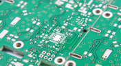
Embedded computers, vision devices, DAQ modules, and much more will all need some memory, whether it’s a Flash chip or a RAM module. Normally, something like a Flash memory chip or a small eMMC module would not be used for temporary storage as the device requires constant rewrites. Instead, if you happen to need a volatile memory solution, you would go for static (SRAM) or dynamic RAM (DRAM). If you need to decide which type of memory to use in your board, keep reading to see some of the basic design guidelines for SDRAM vs. DDR memory modules.
Blog
•
PCB Ground Plane Best Practices in Your Multilayer Stackup
Using a PCB ground plane in a stackup is the first step towards ensuring power and signal integrity, as well as keeping EMI low. However, there are some bad myths about ground planes that seem to persist, and I’ve seen highly experienced designers make some simple mistakes when defining grounds in their PCB layouts. If you’re interested in preventing excess emissions and ensuring signal integrity in your layout, follow these simple guidelines for implementing a PCB ground plane in your next board.
Blog
•
Using an LDO vs. Switching Regulator in Your PCB
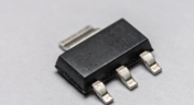
As much as we’d like, the power we supply to electronics isn’t always stable. Real power sources contain noise, they might exhibit power instability, or they dropout unexpectedly. Thankfully, we have power regulators to help prevent some of these problems. For low power devices, we generally see two types of power regulators: a low dropout regulator (LDO) or a switching regulator. You can mix and match these at different points along your power bus, but there’s still the matter of choosing whether to use an LDO vs. a switching regulator in your designs.

Blog
•
Using Altium 365 for Sharing Simulations in the Cloud
Post-layout simulators for your PCB are very valuable tools. If you’re working through a complex design, it’s a good idea to put it through some level of simulation and analysis to evaluate the design before manufacturing. This is all easy with the cloud collaboration tools in Altium 365 and Ansys field solvers thanks to the EDB Exporter utility in Altium Designer. These existing tools in Altium Designer and any of the Ansys field solver utilities give you a simplified way to share design data, EDB files, and simulation results with anyone on your design team.

Blog
•
How to Speed Up Your DFM Report Process in the Cloud
Experienced fabricators will tell you: any design could have some hidden DFM problem that will interfere with manufacturability, quality, or yield. Making use of your design rules is just the start of preventing DFM problems, you’ll want to collaborate with your manufacturer throughout the design process if you want to spot and correct DFM problems. Within Altium Designer, there are multiple reports you can generate for your projects that will help you summarize important information on your board for a client or a manufacturer.
Blog
•
The Digital Engineer's Guide to RF PCB Layout and Routing
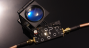
With modern systems running at higher frequencies, incorporating multiple wireless protocols, and interfacing with many analog sensors, advanced designs require knowledge from digital and RF design disciplines. If you’re now starting to work in the RF realm and you need to design an all-analog or mixed-signal system, RF PCB layout will need to become a new specialty. If you’re a digital designer and you’re now jumping into high-frequency analog design, keep reading to learn more about RF PCB layout and routing.
Blog
•
Microstrip Ground Clearance: How Close is Too Close?
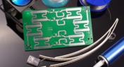
If you take a look at any guidelines for controlled impedance traces, you’ll clearly see that the trace width is calculated without any ground pour near the trace. However, most designers will state that unused areas on each PCB layer should be filled in with grounded copper pour. If you bring some ground pour near a microstrip, you’ve now formed a coplanar waveguide arrangement. So now the question becomes, how much microstrip to ground clearance do you need to ensure you’ve hit your impedance goals?
Blog
•
PCB Layout Guidelines for Switching Power Supplies and Regulators
In this article, I want to briefly focus on how power supplies and regulators are different, although this should already be clear to most designers. For a power supply and for a PCB with an on-board regulator, the switching regulator layout will be a major determinant of overall system performance. Therefore, we’ll largely look at some layout guidelines for switching power supplies in terms of regulator layout.

Blog
•
PCB Sharing and What Data You Can Share in Altium 365
Altium 365 is giving design teams a new way to share and manage their design data. Most users are probably aware of project-level and component-level PCB sharing features, but sharing actually extends down to the level of individual files thanks to the managed content system within Altium 365. If you’ve ever wanted a single place to store and manage all of your design data, then Altium 365 is here to help you and your team stay organized.



On-Demand Webinar
•
Jun 12, 2025
Proactive Lifecycle Management: Preventing Obsolescence Before It Hits


On-Demand Webinar
•
Apr 23, 2025
Collaborative Design Review: Ensuring Quality from Schematics to Supply Chain

On-Demand Webinar
•
Apr 22, 2025
From Prototype to Production: Optimizing BOM Costs Without Compromising Quality with Part Analytics


On-Demand Webinar
•
Apr 9, 2025
Component Selection in Altium Designer: Making Data-Driven Decisions with Data Integrations
On-Demand Webinar
•
Mar 25, 2025
Unlocking the full potential of your design team with Altium's enterprise solution

On-Demand Webinar
•
Jan 24, 2024
Discover How Altium Designer 24 Revolutionizes Team Dynamics in PCB Design


