Welcome, Guest

Sign in to learn, create, and do more with the product you love.

News & Updates

Filters:
Tag
NEW
Embedded thumbnail for HDI PCB Design Review: nRF52840 Via Sizing & Stack-Up Best Practices
How-To's
HDI PCB Design Review: nRF52840 Via Sizing & Stack-Up Best Practices

Explore key HDI design strategies, from calculating aspect ratios and optimizing pad diameters to managing drill tolerances and refining stack-ups for improved signal integrity. This comprehensive review highlights practical solutions to common HDI challenges, including via-in-pad layouts, clearance violations, and layer thickness adjustments for both mechanical and laser drilling processes.

Embedded thumbnail for 13 Common PCB Problems & How to Fix Them in Altium
How-To's
13 Common PCB Problems & How to Fix Them in Altium

Stop wasting time on manufacturing rework. This guide shows you how to set up Altium’s design rules to prevent the 13 PCB issues that most often derail production ensuring your boards are built right the first time.

Blog
Building a Model Context Protocol Server for Arduinos

This guide walks you through creating an MCP server that turns AI interactions with Arduino into a predictable, automated process handling tasks like board listing, compilation, and serial communication via a fast, menu‑driven interface. Skip the guesswork of prompt nudging and reduce the risk of unintended device issues.

Embedded thumbnail for What's Inside Your MCU Module?
How-To's
What's Inside Your MCU Module?

Are you curious about what’s inside a microcontroller module? Join us as we take a closer look at the Texas Instruments CC3235 Wi-Fi module under the microscope. In this video, we’ll explore its key components, including the microcontroller, flash memory, and RF circuitry, and explain how they work together to power the module.

Embedded thumbnail for Altium Harness Design Tutorial - From Schematic to 3D Layout
How-To's
Altium Harness Design Tutorial - From Schematic to 3D Layout

Design professional harness systems in Altium with confidence. Follow this comprehensive tutorial to learn multiboard project setup, create wiring diagrams, visualize in 3D, and produce manufacturing-ready documentation complete with ECAD-MCAD integration for precise wire length measurement.

Blog
Getting Started with the GreenPAK Introduction Kit

Take your first steps into mixed-signal design with the Renesas GreenPAK Introduction Kit. Ari Mahpour shows how to design, simulate, and validate a clock divider project, making it easy for beginners to start experimenting with programmable mixed-signal devices.

Embedded thumbnail for Arduino to Custom PCB: Professional Design Transformation
How-To's
Arduino to Custom PCB: Professional Design Transformation

Discover how to upgrade your Arduino Nano-based PCB design into a professional, custom PCB. This tutorial walks through the process of replacing development boards with individual components to create a production-ready design, using a real drone project as the example.

Blog
Smarter Electronic Part Sourcing for Automotive Purchasing Professionals

Targeted at procurement professionals in the automotive industry, the article outlines the evolving pressures of sourcing components for electrified and connected vehicles. It highlights Octopart’s ecosystem as a unified tool that centralizes availability, compliance, pricing, and lifecycle intelligence to optimize sourcing efficiency.

Embedded thumbnail for PCB Library Management: One Library or Many?
How-To's
PCB Library Management: One Library or Many?

This detailed guide walks you through the pros and cons of each approach and offers proven strategies for managing component data, whether you're an independent designer or overseeing libraries for an entire organization.

Blog
Stack-Up to Success: Avoid the Pitfalls

"Stack‑Up to Success" highlights how a carefully planned PCB stack‑up is foundational to preventing warpage, managing impedance, and avoiding manufacturing delays by clearly communicating layer construction, materials, and tolerance requirements to fabricators.

Embedded thumbnail for Coming Soon: Sawtooth Rounding Support for Length Tuning
New in Altium Designer 25
Coming Soon: Sawtooth Rounding Support for Length Tuning

Sawtooth Rounding for Length Tuning improves signal‑path accuracy by applying controlled corner‑rounding to sawtooth geometries during both Interactive Length Tuning and within‑pair matching in the Auto Tuning engine. Discover this capability and additional innovations on our Coming Soon page.

Embedded thumbnail for Coming Soon: Z-Axis Clearance Rule
New in Altium Designer 25
Coming Soon: Z-Axis Clearance Rule

The Z-Axis Clearance Rule checks the shortest distance between copper features on different layers in a PCB design. It is available in both the Constraint Manager and the legacy PCB Rules Editor. Discover more new features in Altium on our Coming Soon Page.

Embedded thumbnail for Coming Soon: Advanced Polygon Pour Engine
New in Altium Designer 25
Coming Soon: Advanced Polygon Pour Engine

Now supports true arcs instead of approximated curves in copper pours. This enhanced engine marks a major advancement in the polygon pour process in Altium Designer, delivering smoother and more accurate copper shapes. Native arc rendering improves visual quality and helps ensure cleaner, more professional PCB designs.

Tag
What is the PCB Supply Chain?
Blog
What is the PCB Supply Chain?

The PCB supply chain encompasses multiple components, raw materials, and the PCB itself. PCBs and PCB assemblies are often the most technically complex components that are purchased for electronic assemblies and products. The complexity of modern PCBs leads to several challenges for a supply chain management team that may be significantly different when compared with other commodities the team manages. In this brief guide, we'll look in-depth at the PCB supply chain, and specifically what falls within the purview of a procurement and supply chain management team.

What is mode conversion
Blog
A Guide to Mode Conversion, Its Causes, and Solutions

On interconnects, such as board-to-board connections or cascaded transmission line arrangements, you have an important EMC compliance metric that is sometimes overlooked. This is mode conversion, which can be visualized in an S-parameter measurement for differential and common-mode signal transmission. In this article, we’ll look at a short overview of mode conversion in high-speed design with some examples from common differential standards.

Pad and via sizing
Blog
PCB Via Size and Pad Size Guidelines

There are some aspects of PCB design and layout that seem deceptively simple, and yet they have a complex answer that is related to many important aspects of manufacturing. One of these design aspects is the match between PCB via size and pad size. Obviously, these two points are related; all vias have a landing pad that supports the via and provides a place to route traces into a via pad. However, there are some important sizing guidelines to follow when the matching pad and via sizes, and this match is an important element of DFM and reliability.

Differential Microstrip Impedance
Blog
Differential Microstrip Impedance Calculator

Are you looking for a free tool that you can use to calculate the impedance of differential microstrips? We created a simple tool you can use to calculate differential microstrip impedance for a given geometry and dielectric constant. If you’ve been looking for an accurate differential microstrip impedance calculator, then the calculator below is certainly one of the best free tools you’ll find on the internet before you start using field solvers to determine differential pair impedance.

PCB DFM Check
Blog
Getting Through a PCB DFM Check

In this article, we’ll discuss the key design features to implement, and steps to take prior to fabrication that will help prevent some common DFM problems. I’ll also provide examples of where I commonly see these PCB DFM problems in signal integrity circuits.

Spreading Inductance
Blog
What is Spreading Inductance?

If you’re working with a high-speed digital component, there are some simple power integrity rules that should be followed. However, there is one quantity that is sometimes ignored when building a PDN impedance simulation: the spreading inductance of your plane pair. Here are some points designers should know about the spreading inductance of a plane pair.

PCB Design Basics for New Designers
Blog
PCB Design Basics for New Designers

In this article, I’ll present some design basics that every new designer should follow to help ensure their design process is successful. Some of these points may challenge the conventional view of how circuit boards are constructed, but they are intended to help balance low noise signaling, manufacturability, and ease of solving a layout.

Selecting Materials for High Voltage PCB Design and Layout
Blog
Selecting Materials for High Voltage PCB Design and Layout

High voltage PCBs are subject to certain safety and reliability concerns that you won’t find in most other boards. If your fabrication house specializes in high voltage PCBs and keeps materials in stock, they can likely recommend a material set, as well as a standard stackup you might use for certain voltage ranges and frequencies. If you need to choose your own materials, follow the tips below to help you narrow down to the right material set.

Via tenting in PCB Layout
Blog
When to Use Tented Vias in Your PCB Layout

There are some guidelines I see many designers implement as a standard practice, often without thinking about it. Some of these practices are misunderstood or implemented without best practices. Others are implemented without thinking about the potential problems. One of these is the use of tented vias, which is sometimes implemented in a PCB layout by default. Is this always the right practice?

Capacitive load termination
Blog
How to Impedance Match and Terminate Capacitive Loads

The idea of a purely capacitive load is something of a fallacy. Yes, capacitors exist, but all capacitors are non-ideal, and it is this deviation from a theoretical capacitance that determines how to impedance match a load that exhibits capacitive behavior. Let’s take a look at this important aspect of interconnect design and see what it really means to terminate a capacitive load.

Using Altium 365 Over Your Vanilla Version Control System
Blog
Using Altium 365 Over Your Vanilla Version Control System

There are all sorts of version control systems out there that people have been using with their PCB design software. As discussed in Why Use a Version Control System, we looked at different options ranging for local hard drive storage to sophisticated online revisioning systems. In this article we will be reviewing the differences between a standard VCS and Altium 365.

Why Use a Version Control System in PCB Design
Blog
Why Use a Version Control System in PCB Design

Version Control Systems (VCS) have been around for many decades within the software world but can be surprisingly new to some folks in the electronics design industry. This article will cover what a VCS is, what it does, and why you should be using one for your PCB design projects.

IPC 6012 Class 3 Annular Ring
Blog
Meeting Standards: IPC 6012 Class 3 Annular Ring

Designers often conflate leftover annular ring and pad sizes - they need to place a sufficiently large pad size on the surface layer to ensure that the annular ring that is leftover during fabrication will be large enough. As long as the annular ring is sufficiently large, the drill hit will not be considered defective and the board will have passed inspection. In this article, I'll discuss the limits on IPC-6012 Class 3 annular rings as these are a standard fabrication requirement for high-reliability rigid PCBs.

PCB fabrication notes
Blog
Decoding PCB Fabrication Notes

Sending a board out for fabrication is an exciting and nerve-wracking moment. Why not just give your fabricator your design files and let them figure it out? There are a few reasons for this, but it means the responsibility comes back to you as the designer to produce manufacturing files and documentation for your PCB. It’s actually quite simple if you have the right design tools. We’ll look at how you can do this inside your PCB layout and how this will help you quickly generate data for your manufacturer.

HDI PCB design and HDI PCB manufacturing process
Blog
Design Basics for HDI and the HDI PCB Manufacturing Process

As the world of technology has evolved, so has the need to pack more capabilities into smaller packages. PCBs designed using high-density interconnect techniques tend to be smaller as more components are packed in a smaller space. An HDI PCB uses blind, buried, and micro vias, vias in pads, and very thin traces to pack more components into a smaller area. We’ll show you the design basics for HDI and how Altium Designer® can help you create a powerful HDI PCB.

All About PCB Test Points
Blog
Is It Printed or a Component? All About PCB Test Points

Test points in your electronic assembly will give you a location to access components and take important measurements to verify functionality. If you’ve never used a test point or you’re not sure if you need test points, keep reading to see what options you have for test point usage in your PCB layout.

Tag
Embedded thumbnail for Creating a PCB Footprint Silkscreen Overlay
How to create a PCB Footprint
Creating a PCB Footprint Silkscreen Overlay

When creating a PCB footprint in Altium Designer creating a silkscreen overlay is an important requirement. We’ll go over the standards for creating a silkscreen overlay for a footprint and the steps to creating one, such as constructing lines and measuring distance of objects and primitives.

Tuning
What's New in 22.7
Ability to Change Tuning Object Layer Properties

Design of high-speed PCBs becomes easier with this latest release. Now, when you need to quickly move tuning elements to a different layer, you can do so from the Properties panel with a single click.

Tuning
What's New in 22.7
更改调节对象层属性功能

本次发布后,即可更加轻松地进行高速PCB设计。现在,当您需要将调节元件快速移动到其他层时,仅需单击一次即可从Properties面板中执行此操作。

Simulation models
What's New in 22.7
Auto-assign Simulation Models for Components without Models

This latest version of Altium Designer makes schematic simulation even easier. System intelligence automatically recognizes SPICE models and assigns them to components from available sources.

Simulation models
What's New in 22.7
自动分配不含模型的元件仿真模型

最新版Altium Designer将确保您能够更加轻松地进行原理图仿真。系统智能自动识别 SPICE 模型并将其分配给可用来源的元件。

Paste
What's New in 22.7
Control of Paste Mask Output for Variants

Output data needs to be as accurate as possible. For multi-variant designs you can now ensure that the paste mask is only displayed where it is really needed.

Paste
What's New in 22.7
变量助焊层输出控件

输出数据需要尽量准确。对于多变量设计,您现在可以确保将助焊层仅显示在真正需要的位置。

Embedded thumbnail for Adding Designators for Assembly Drawings
How-To's
Adding Designators for Assembly Drawings

Designators for assembly drawings are added on the assembly layer. This video shows how to add the designators.

Embedded thumbnail for Stackup Material Library
How to work with Layer Stack Manager
Stackup Material Library

In this video we will learn more about the Altium designers Layer Stack Mangers built-in materials library, and how to add new material and use it in our board stack. We will also look at how we can save the user materials to an xml format.

Embedded thumbnail for Placing Footprint Pads
How to create a PCB Footprint
Placing Footprint Pads

Every footprints needs proper pad placement to ensure trace connectivity. Placing pads is the first step towards footprint creation.

Embedded thumbnail for Setting the Transparency for Layers and Primitives
How-To's
Setting the Transparency for Layers and Primitives

Customize your workspace by setting the transparency of layers and primitives in the PCB.

Embedded thumbnail for Create New Via Types Using the Layer Stack Manager
How to work with Layer Stack Manager
Create New Via Types Using the Layer Stack Manager

In this video, we will learn how to create new via types using the Layer Stack Manager, and how to create new Routing Via design rules using the PCB Rules and Constraints Editor. We will also explore how to use the different types of Via during interactive routing.

Embedded thumbnail for How to Create a Copper Board Report
How-To's
How to Create a Copper Board Report

This video will show how to create a copper board report in your PCB which can be useful for copper balance in DFM process

Embedded thumbnail for Stackup Creation and editing
How to work with Layer Stack Manager
Stackup Creation and editing

This video shows how to view and edit the PCB Layer Stack, select materials and add new layers

Embedded thumbnail for Configuring Your PCB Library
How to create a PCB Footprint
Configuring Your PCB Library

It is important to have accurate footprints to manufacture your PCB. Learn how to configure your PCB library to facilitate footprint creation.

Global parameters
What's New in 22.6
Quick Browsing of Parameters for a Board

Parametric information for your board is now conveniently available from the Properties panel. A single, convenient location with which to browse system, calculated and user-defined parameters, and place as needed in the form of special strings.

Tag
Integrating Requirements June 2025 Webinar
On-Demand Webinar May 28, 2025
Integrating Requirements into Your PCB Design Workflow
Join our webinar where you will learn about integrated requirements tools who can help you eliminate late-stage design changes, AI support through system requirements and integration of design requirements directly in PCB Design. Don't miss it, register now!
Streamlining Team Collaboration
On-Demand Webinar Apr 17, 2025
Streamlining Team Collaboration in Industrial PCB Projects
Join us for our upcoming webinar to discover how Altium Designer and Altium 365 can transform your team’s collaboration and take your PCB design projects to the next level. Attend for a chance to win free access to the Altium 365 Training Bundle.
PCB CoDesign Webinar
On-Demand Webinar Jan 24, 2024
Discover How Altium Designer 24 Revolutionizes Team Dynamics in PCB Design
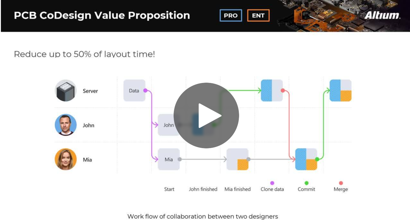
Expand your collaboration skills and stay ahead of the curve with PCB CoDesign. Design teams often grapple with prolonged design cycles and coordination issues, leading to delays and inefficiencies. In the current landscape, design processes are hindered by fragmented collaboration, resulting in increased layout times and difficulties in synchronizing design updates.