Welcome, Guest

Sign in to learn, create, and do more with the product you love.

News & Updates

Filters:
Tag
NEW
Blog
What Is BOM Management? A Practical Guide to Avoiding Costly Part Mismatches

From design to production, effective Bill of Materials (BOM) management is critical to ensuring smooth collaboration between engineering, procurement, and manufacturing teams. In this practical guide, we break down proven strategies for structuring, maintaining, and synchronizing your BOM to prevent costly mistakes and accelerate time-to-market.

NEW
Blog
Requirements Portal Introductory Tutorials

This series of guided demos shows how the Altium Requirements Portal transforms scattered requirement spreadsheets and emails into traceable, version-controlled data that stays aligned with your PCB design efforts.

NEW
Embedded thumbnail for PCB Design Tools for Every Team Size: Altium's New Approach
How-To's
PCB Design Tools for Every Team Size: Altium's New Approach

Explore how Altium is transforming PCB design with software solutions built for teams of every size. In this exclusive PCB West 2025 interview, Justin Sears highlights the key distinctions between Altium Develop and Altium Agile helping you identify the ideal platform for your design needs.

NEW
Blog
Bridging the Gap: When to Use Rigid-Flex Instead of Flex & Connector

Discover when a rigid-flex PCB is a better choice than a separate flex circuit and connector, especially for designs requiring compact packaging, repeated motion or high reliability. The article emphasizes that although rigid-flex needs more upfront planning and fabrication collaboration, it often pays off in simpler assemblies and improved performance.

Embedded thumbnail for PCB Design: Sequential Lamination vs Sub-Lamination
How-To's
PCB Design: Sequential Lamination vs Sub-Lamination

Explore the key distinctions between sequential lamination and sub-lamination techniques, and learn how each approach influences microvia placement, board complexity, and design flexibility in high-density interconnect (HDI) circuit board fabrication.


Embedded thumbnail for PCB Design Review: Power Meter Layout Deep Dive
How-To's
PCB Design Review: Power Meter Layout Deep Dive

Gain practical insights into PCB design with an in-depth power meter project review, covering parameter optimization, BOM control, and IPC-compliant high-voltage spacing.

Embedded thumbnail for Drawing Tools for Pro Schematics in Altium
How-To's
Drawing Tools for Pro Schematics in Altium

In our brand-new tutorial, you’ll learn how to create professional-looking schematics in Altium using built-in drawing tools and features. We’ll show you how to add custom title blocks, revision histories, tables of contents, block diagrams, and color schemes to make your schematics stand out.

Blog
How Structural Electronics Enables 3D, Flexible, and Wearable Integration

Structural electronics integrates electronic functionality directly into the physical structure of a product, eliminating the need for traditional circuit boards. This article examines how advances in materials, additive manufacturing, and flexible substrates are enabling compact, 3D, and wearable systems with enhanced performance and design freedom.

Embedded thumbnail for 3 GHz RF Amplifier Deep Dive
How-To's
3 GHz RF Amplifier Deep Dive

Check out our design review of a 3.6 GHz RF amplifier! This in-depth analysis highlights schematic issues, PCB layout challenges, and key RF design principles to help you build better high-frequency circuits.

Embedded thumbnail for The Right Way to Use SIG/GND/PWR/SIG Stackups
How-To's
The Right Way to Use SIG/GND/PWR/SIG Stackups

Find out how to properly implement signal-ground-power-signal stackups in 4-layer PCB designs. Check out our tutorial from Zach Peterson, where he explains when to use dedicated power layers, how to route signals correctly over split power planes, and common mistakes to avoid for optimal EMI performance and signal integrity.

Embedded thumbnail for Altium Training - Design Environment: Documents and Panels
Altium Training
Altium Training - Design Environment: Documents and Panels

In our new tutorial, we explore different panel display modes, including docked, floating, and tabbed grouping arrangements. Effective panel management is essential for creating an efficient design environment tailored to your specific workflow requirements.

Blog
Most Common Causes of PCB Assembly Rework and Scrap

Many PCB assemblies fail not because of exotic faults, but due to basic issues like incorrect BOM entries or footprint mismatches that force rework or scrap. This article dives into the most common causes and how to prevent costly defects in your design-to-manufacturing process.

Embedded thumbnail for Mechanically Drilled Blind & Buried Vias: PCB Design Rules Explained
How-To's
Mechanically Drilled Blind & Buried Vias: PCB Design Rules Explained

Discover the essential design rules and manufacturing processes for mechanically drilled blind and buried vias in PCB layouts in this comprehensive tutorial. We cover the stack drill-and-plate fabrication process, aspect ratio limitations, sub-lamination design, and copper weight considerations. You’ll also learn how these vias differ from HDI microvias and gain a clear understanding of the critical design constraints needed for successful PCB manufacturing.

Blog
Behind the Scenes with AI Embedded Development

Forget one-shot AI hacks Ari Mahpour shows the thoughtful, sustainable way to integrate AI into embedded firmware development. Learn the core principles (planning gate, HAL abstraction, observability, timeout design) that can help you push your efficiency 5-10 times in real hardware projects.

Embedded thumbnail for Altium Training - Design Environment: Navigation with Schematic Workspace
Altium Training
Altium Training - Design Environment: Navigation with Schematic Workspace

Discover the most important navigation techniques for the schematic workspace using both mouse and keyboard controls. In this tutorial video, you’ll learn how to use the View menu commands for document fitting, area zooming, and object selection, along with advanced navigation shortcuts. Master mouse-based panning and zooming, explore Ctrl key combinations, and practice arrow key movements - all designed to simplify your workflow in the PCB design process.

Blog
We're heading to PCB West 2025!

Join Altium at PCB West 2025 in Santa Clara, CA, on October 1! Stop by Booth 300 for the official launch of the new Altium platform, built on the foundation of Altium Designer and Altium 365. Be sure to check out our live demos of Altium Develop and Altium Agile.

Tag
Blog
The Ultimate Introduction to High-Speed Signal Integrity for PCB Designers

High-speed signal integrity is essential in PCB design to ensure data accuracy and system reliability. Key issues like impedance mismatches, crosstalk, and signal reflections need to be addressed through strategies such as controlled impedance traces, differential pairs, and suitable material choices. Check out our first article of the series about this topic.

Blog
Multi-Board PCB Signal Integrity: A Complete Guide

Our new article on signal integrity in multi-board PCBs covers essential aspects like connector pinouts, cable designs, and interconnect strategies. These factors ensure reliable performance in high-speed applications across industries such as military, aerospace, and AI.

Blog
Pi.MX8 Project - Board Layout Part 4

We invite you to explore a new chapter in the PiMX8 Project, focusing on the final stages of PCB layout design for the Pi.MX8 compute module. This installment covers critical topics such as routing power planes and signal delay tuning, essential for ensuring proper functionality and performance.

Blog
How Thermoformed Flex PCB’s are Designed and Fabricated

Thermoformed flexible PCBs are specially designed and fabricated by heating and molding them into specific shapes, making them suitable for compact and complex applications like automotive dashboards and wearable devices. This process involves precise temperature control and careful handling to ensure durability and quality. Discover more from Tara Dunn's new article.

Blog
Boost Connection Integrity and Design Efficiency with Wire Bonding

Altium Designer's wire bonding feature enhances PCB design by supporting chip-up configurations for Chip on Board (CoB) designs. It offers easy validation of bond wiring in 3D views, ensuring accurate and efficient design processes. Check more about this feature on Altium's new feature page.

Blog
How High Frequency SMD Passives Work in a PCB Layout

High-frequency surface-mount device (SMD) passives like resistors and capacitors play a crucial role in PCB layouts, particularly in circuits operating above 1 GHz. Our article explores how these components function at high frequencies, their operational limits, and the importance of considering parasitic elements in design.

Blog
Essential DFM Tips for Aerospace Projects

Design for Manufacturing (DFM) is a crucial aspect of aerospace projects. This process ensures high-quality designs that meet the unique challenges of the aerospace industry, such as extreme conditions and stringent reliability standards. Learn more about essential DFM tips in our brand-new article.

Altium 365 New Website
Blog
Altium 365 now has its own website!

Discover everything you need to know about Altium 365 and experience our suite of applications for secure, seamless, and streamlined collaboration. Visit now to explore how to streamline your electronic product development.
 

Blog
Altium Designer: Leading the Charge in PCB Design Innovation

In the dynamic field of electronics design, Altium Designer stands out as a pioneer, continuously advancing the boundaries of PCB (Printed Circuit Board) design. Discover the latest innovations in 3D-MID design, high-speed design, and interactive routing in this new article by David Marrakchi.

Blog
What Is Solder Mask Expansion and Which Value Should You Use?

Check out our new article explaining how to ensure sufficient pad area for soldering, manage misregistration tolerance, and maintain proper solder dams between components. It also highlights the role of collaboration with fabrication houses and the use of CAD tools in defining land patterns for advanced electronics designs.

Blog
Pi.MX8 Project - Board Layout Part 3

We continue our exploration of the Pi.MX8 open-source computer module project. In this new installment, we focus on routing planning and then cover all the layers' routing with all the details you need to know if you want to prepare a similar project.

Blog
Mastering Blind and Buried Vias

Check our compilation of essential resources you'll need to use blind and buried vias successfully in an HDI PCB. In our brand new article, we present the main and most valuable information about this technology, which may not be new but is still highly useful in High-Density Interconnect projects.

Tag
Embedded thumbnail for Design RF PCB: routing (any angle, arc)
How-To's
Design RF PCB: routing (any angle, arc)

It is worth taking a responsible approach to the shape and size of the RF signal conductors. In this video we will cover some practical aspects of working with routing such nets in Altium Designer.

Embedded thumbnail for Draftsman Document: Snapping
How-To's
Draftsman Document: Snapping

Snapping using the grids and snapping tools in Altium Designer’s Draftsman Editor gives you a lot of control over how you create and annotate primitives and components. We’ll show you how easy it is to use snapping in the Drafstman Editor.

Further Enhancements to Sheet Cross-referencing
What's New in 22.3
Schematic Capture Improvement

Adding cross-references to the project allows you to easily follow the connective flow of nets between the schematic sheets in a project. 

Further Enhancements to Sheet Cross-referencing
What's New in 22.3
原理图输入改进

您可以通过向项目添加交叉引用,轻松跟踪项目中原理图图纸之间的网络连接流。

Embedded thumbnail for High Speed: XSignals
How-To's
High Speed: XSignals

You can create, configure, and utilize xSignals in Altium Designer to make your design process more efficient and effective. We’ll show you how to do it manually, using the more comprehensive Create xSignals command, and using the xSignal wizard.

Embedded thumbnail for DFM and fab cost/time constraints: What is annular ring and how to configure it
How-To's
DFM and fab cost/time constraints: What is annular ring and how to configure it

The minimum dimension from the wall of the aperture to the edge of the pad is called an annular ring, and we can configure it with Altium Designer. We’ll show you how to get started and manage the annular ring in your design rules.

Embedded thumbnail for Altium 365 Getting Started: Gerber Compare
How-To's
Altium 365 Getting Started: Gerber Compare

The task of comparing different versions of manufacturing files usually arises when the electrical engineer needs to check and confirm the manufacturer's edits or clarify details of changes before starting production. In Altium 365 you can perform an automatic comparison of Gerber files.

Embedded thumbnail for Polygon Pours
Working with Polygons
Polygon Pours

Polygon pours are used to create copper geometries on your board. You can prioritize polygon pour order, hide them to make it easier to work on your board, and repour them to resolve design rule conflicts.

Embedded thumbnail for How to Use the MCAD CoDesigner?
How-To's
How to Use the MCAD CoDesigner?

This video shows how the ECAD and MCAD engineers now can communicate directly while staying within their own design environment. The MCAD engineer is able to push design information directly from their design software straight into Altium Designer. Any changes can be reviewed, accepted, or denied by the receiving party. This process of pushing and reviewing design changes is bi-directional, meaning that both the MCAD or ECAD engineer can push and review changes to the other. 

Embedded thumbnail for Creating Additional Snap Points Using a 3D Model
How to use Snapping
Creating Additional Snap Points Using a 3D Model

Demonstration of using snap points with 3D models and how they can assist in the placement of said models.

Embedded thumbnail for Polygon Connect Styles
Working with Polygons
Polygon Connect Styles

Define how vias and pads connect to polygons with a design rule. Customize the thermal relief width, number, and rotation as well as the air gap width.

Embedded thumbnail for How to work with Component Classes?
How to Work with Classes
How to work with Component Classes?

Modern printed circuit boards can contain a large number of components, which makes them difficult to work with. In this video we will show what component classes can be on a PCB, how to create custom component classes and how they can be useful for us. 

Embedded thumbnail for Create and Snap to a Circular Grid (Polar Grid)
How to use Snapping
Create and Snap to a Circular Grid (Polar Grid)

Instructional on how to create polar grids, how to snap to them, and why you might want to use them.

Embedded thumbnail for How to Connect Polygons to Nets
Working with Polygons
How to Connect Polygons to Nets

This video covers how to easily connect a polygon to a net using just two clicks. With the Properties panel open and a polygon selected, click the "Assign net" button in the Properties panel.

Embedded thumbnail for Altium 365 Getting Started: Gerber Compare
Getting Started with A365
Altium 365 Getting Started: Gerber Compare

The task of comparing different versions of manufacturing files usually arises when the electrical engineer needs to check and confirm the manufacturer's edits or clarify details of changes before starting production. In Altium 365 you can perform an automatic comparison of Gerber files. 

Embedded thumbnail for Altium 365 Getting Started: Schematic Compare
Getting Started with A365
Altium 365 Getting Started: Schematic Compare

The schematic sheets in a project are subject to change over time, and sometimes it may be necessary to compare several different versions and detect differences between them. In Altium Designer you can easily perform an automatic comparison of any revisions of schematic documents. 

Tag
Integrating Requirements June 2025 Webinar
On-Demand Webinar Mag 28, 2025
Integrating Requirements into Your PCB Design Workflow
Join our webinar where you will learn about integrated requirements tools who can help you eliminate late-stage design changes, AI support through system requirements and integration of design requirements directly in PCB Design. Don't miss it, register now!
Streamlining Team Collaboration
On-Demand Webinar Apr 17, 2025
Streamlining Team Collaboration in Industrial PCB Projects
Join us for our upcoming webinar to discover how Altium Designer and Altium 365 can transform your team’s collaboration and take your PCB design projects to the next level. Attend for a chance to win free access to the Altium 365 Training Bundle.
PCB CoDesign Webinar
On-Demand Webinar Gen 24, 2024
Discover How Altium Designer 24 Revolutionizes Team Dynamics in PCB Design
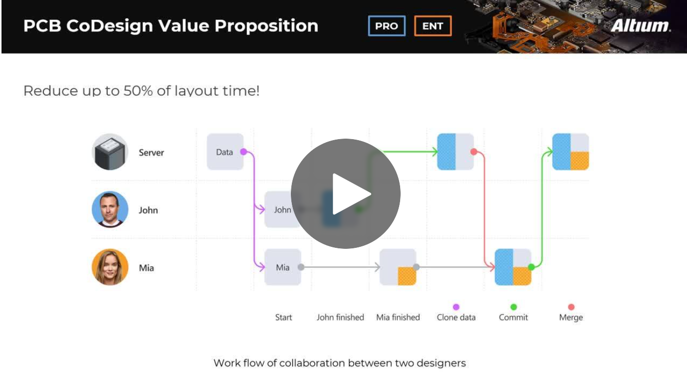
Expand your collaboration skills and stay ahead of the curve with PCB CoDesign. Design teams often grapple with prolonged design cycles and coordination issues, leading to delays and inefficiencies. In the current landscape, design processes are hindered by fragmented collaboration, resulting in increased layout times and difficulties in synchronizing design updates.