Welcome, Guest

Sign in to learn, create, and do more with the product you love.

News & Updates

Filters:
Tag
NEW
Embedded thumbnail for Altium Harness Design Tutorial - From Schematic to 3D Layout
How-To's
Altium Harness Design Tutorial - From Schematic to 3D Layout

Design professional harness systems in Altium with confidence. Follow this comprehensive tutorial to learn multiboard project setup, create wiring diagrams, visualize in 3D, and produce manufacturing-ready documentation complete with ECAD-MCAD integration for precise wire length measurement.

NEW
Blog
Getting Started with the GreenPAK Introduction Kit

Take your first steps into mixed-signal design with the Renesas GreenPAK Introduction Kit. Ari Mahpour shows how to design, simulate, and validate a clock divider project, making it easy for beginners to start experimenting with programmable mixed-signal devices.

Embedded thumbnail for Arduino to Custom PCB: Professional Design Transformation
How-To's
Arduino to Custom PCB: Professional Design Transformation

Discover how to upgrade your Arduino Nano-based PCB design into a professional, custom PCB. This tutorial walks through the process of replacing development boards with individual components to create a production-ready design, using a real drone project as the example.

Blog
Smarter Electronic Part Sourcing for Automotive Purchasing Professionals

Targeted at procurement professionals in the automotive industry, the article outlines the evolving pressures of sourcing components for electrified and connected vehicles. It highlights Octopart’s ecosystem as a unified tool that centralizes availability, compliance, pricing, and lifecycle intelligence to optimize sourcing efficiency.

Embedded thumbnail for PCB Library Management: One Library or Many?
How-To's
PCB Library Management: One Library or Many?

This detailed guide walks you through the pros and cons of each approach and offers proven strategies for managing component data, whether you're an independent designer or overseeing libraries for an entire organization.

Blog
Stack-Up to Success: Avoid the Pitfalls

"Stack‑Up to Success" highlights how a carefully planned PCB stack‑up is foundational to preventing warpage, managing impedance, and avoiding manufacturing delays by clearly communicating layer construction, materials, and tolerance requirements to fabricators.

Embedded thumbnail for Coming Soon: Sawtooth Rounding Support for Length Tuning
New in Altium Designer 25
Coming Soon: Sawtooth Rounding Support for Length Tuning

Sawtooth Rounding for Length Tuning improves signal‑path accuracy by applying controlled corner‑rounding to sawtooth geometries during both Interactive Length Tuning and within‑pair matching in the Auto Tuning engine. Discover this capability and additional innovations on our Coming Soon page.

Embedded thumbnail for Coming Soon: Z-Axis Clearance Rule
New in Altium Designer 25
Coming Soon: Z-Axis Clearance Rule

The Z-Axis Clearance Rule checks the shortest distance between copper features on different layers in a PCB design. It is available in both the Constraint Manager and the legacy PCB Rules Editor. Discover more new features in Altium on our Coming Soon Page.

Embedded thumbnail for Coming Soon: Advanced Polygon Pour Engine
New in Altium Designer 25
Coming Soon: Advanced Polygon Pour Engine

Now supports true arcs instead of approximated curves in copper pours. This enhanced engine marks a major advancement in the polygon pour process in Altium Designer, delivering smoother and more accurate copper shapes. Native arc rendering improves visual quality and helps ensure cleaner, more professional PCB designs.

Embedded thumbnail for How to Design Rigid-Flex PCB Stackups from Scratch
How-To's
How to Design Rigid-Flex PCB Stackups from Scratch

Watch this tutorial to learn the fundamentals of Rigid-Flex design. We cover everything from understanding polyimide materials and adhesive layers to building complex, multi-layer Rigid-Flex constructions that are ready for manufacturing.

Blog
How to Effectively Use Jira for Hardware Development Projects

Originally built for software development, Jira has become a popular tool for agile project management across various industries. Our new article explores how hardware teams can leverage core Jira features and adapt agile principles to suit the unique needs of hardware development.

Embedded thumbnail for How to Draw Antipads - Complete Tutorial
How-To's
How to Draw Antipads - Complete Tutorial

Discover how to draw and define antipads in Altium with this complete tutorial. Learn three different methods for creating antipads around vias. From simple design rules to advanced polygon cutouts for both basic and complex PCB designs.

Embedded thumbnail for Do PCB Manufacturers Actually Look at Fabrication Drawings?
How-To's
Do PCB Manufacturers Actually Look at Fabrication Drawings?

Explore this in-depth tutorial featuring real fabrication drawings, stackup specifications, and drill tables - all created using Altium Designer’s Draftsman tool. Learn essential insights into PCB data management and manufacturing requirements from an industry perspective.

Embedded thumbnail for Compensating Transmission Line Losses in a PCB Calculator
How-To's
Compensating Transmission Line Losses in a PCB Calculator

This tutorial uncovers the key difference between ideal, lossless impedance calculations and real-world signal behavior giving you practical techniques to design controlled impedance PCBs that deliver reliable performance.

Tag
Blog
PCB Layout Guidelines for Switching Power Supplies and Regulators

In this article, I want to briefly focus on how power supplies and regulators are different, although this should already be clear to most designers. For a power supply and for a PCB with an on-board regulator, the switching regulator layout will be a major determinant of overall system performance. Therefore, we’ll largely look at some layout guidelines for switching power supplies in terms of regulator layout.

PCB Sharing - What Data You Can Share in Altium 365
Blog
PCB Sharing and What Data You Can Share in Altium 365

Altium 365 is giving design teams a new way to share and manage their design data. Most users are probably aware of project-level and component-level PCB sharing features, but sharing actually extends down to the level of individual files thanks to the managed content system within Altium 365. If you’ve ever wanted a single place to store and manage all of your design data, then Altium 365 is here to help you and your team stay organized.

Power Supply Components on PCB
Blog
How to Combat Power Supply EMI in Your PCB

Power supplies are one of those systems we all tend to take for granted. Everyone’s first task in power supply design is usually to ensure the voltage and current output reach the desired level, probably followed by thermal considerations. However, due to safety issues, EMC requirements, the use of higher PWM frequencies, and the need for smaller packaging, power supply EMI should be a major design consideration. With that being said, what are the major sources of power supply EMI, and how can power supply designers keep them in check?

Free footprint library resources
Blog
Leveraging the Free Footprint Community to Design at Lightning Speed

Designing footprints is a job most people hate. It’s tedious, time-consuming, and doesn’t result in much except, well, a footprint. Companies now realize this pain point and offering designers free, well-designed PCB footprints. Why would they spend their time doing this? In this article, we’re going to review some of the free offerings that exist within the PCB design community. Once you’re armed with this information, you will spend most of your time designing and routing boards instead of pulling your hair out creating footprints all day.

PCB Motherboard with Multiple Slots with RAM Memory Installed, and Other System Hardware
Blog
Designing for Multiple PCBs in the Same Project

The majority of our PCB designs sit as a single PCB under our Altium Designer projects. It sometimes happens that we have a single project that requires multiple PCBs with various stuffing options, but when it happens, a lot of us tend to get stuck. How do you handle the exact change across both projects? How do you guarantee those changes to be identical? This article will review an approach to managing multiple PCB designs within a single project, ensuring your single source of truth.

EMI and thermal challenges in 5G design
Blog
Designing 5G Devices

The next stage in the evolution of mobile telephony is here with the roll-out of 5G. The designer looking to incorporate functionality to handle 5G signals into their circuits will face some challenging issues. So, what’s so special about 5G?

PCB tracks
Blog
All About Your PCB Trace Length: How Long is Too Long?

The maximum PCB trace length you can place between two components depends on multiple factors, such as signaling protocol, component specification, losses in PCB laminate, and skew. With all this in mind, let’s look at where losses accumulate along the channel.

LDO
Blog
Using an LDO vs. Switching Regulator in Your PCB

For low power devices, we generally see two types of power regulators: a low dropout regulator (LDO) or a switching regulator. You can mix and match these at different points along your power bus, but there’s still the matter of choosing whether to use an LDO vs. a switching regulator in your designs. If you’ve ever wondered how these decisions are made and when to use each type of regulator, just know that there is more to this decision than simply looking at the input/output voltage/current.

Natural flux
Blog
What They Don’t Teach You About Fluxes

PCB fabrication is an extremely complex technological topic that deserves recognition as the most fundamental part of PCB engineering. Unless connectors, conductive adhesive, wire-bonding, or zebra-tape are used, in the modern electronics industry it’s always necessary to use some kind of flux during the soldering process to create an electric connection. In this article, we’ll discuss fluxes — what they are, what they are made of (yes, there is going to be a lot of chemistry, don’t be scared), how they should be used, and in what direction the industry is going.

PCB with ice for best cooling
Blog
Thermal Management for Integrated Circuits

As anyone who designs and builds electronic devices knows, the device will generate heat when it’s switched on. Wherever current flows through an impedance, energy losses will manifest themselves as heat. Integrated circuit packaging is getting smaller to meet the trend for more compact devices but at the cost of poorer thermal properties. This article describes the basic thermal management approaches to consider in your next designs. 

Blog
Anatomy of Latitude Part Two: "Thread with a Needle” in the context of energy

We continue to explore the magic of energy conversion in a PWM transducer. Why is it magic? Theoretically, in a PWM transducer this happens without losses, isn't that magic? A PWM transducer, like a tailor with scissors, cuts the “fabric of energy” into pieces, and then, like a sewing machine, stitches the pieces of energy into a dress - DC Magnitude. What is a constant component and how can we get it? Let's explore!

Pulse Width Regulation Module
Blog
Anatomy of Latitude Part One: Pulse Width Modulation (PWM) as a Result of the Evolution of Linear Systems

There are different techniques in the world of technology to achieve various goals, both final and intermediate. Some techniques are so successful that they are commonly used with high efficiency. Electronics is no exception. The greatest example is the use of Pulse Width Modulation (PWM) signals (energy), which is applied in any modern electronic device. To apply PWM effectively, it is necessary to understand the engineering difficulties that engineers faced in the past, and the thoughts and ideas that subsequently were combined into effective, complete PWM power solutions.

Electrolytic capacitor
Blog
What Influences Electrolytic Capacitor Lifespan?

If you speak with a bunch of design engineers, you might quickly form the opinion that the electrolytic capacitor has a particularly dubious reputation. A faulty electrolyte mix used in these types of capacitors led to premature device failures, and quite often, a “bit of a mess” was made to the PCBs on which they were soldered. However, despite the problem of the capacitor plague, this article is focusing on helping the designer understand how to get many more years of useful life from an electrolytic capacitor.

Elegant writing
Blog
Creating Elegant and Readable Schematics

A schematic drawing will not only tell your PCB design software what needs to connect where, but it also communicates the purpose of a circuit to other people. It’s easy to create a schematic, but it can be harder to make a helpful schematic that can be quickly and easily read and comprehended by the reader. In this guide, based on years of industry experience, we will show you how to improve your schematic layout so that your designs are elegant and readable.

Copper rings
Blog
Must Have Rapid Prototyping Tools

Suppose your job involves rapidly iterating designs or creating a wide variety of products for clients. In that case, there are some essential tools available that can save you a tremendous amount of time, bringing high engineering risk devices to completion successfully. Whether you’re working on internal projects or developing high mix devices for clients as a consulting or freelance firm, these indispensable tools will help you ship a higher quality product in less time. 

Blog
Best Practices for Sharing PCB Files vs. Sharing PCB Projects

Even though today’s cloud platforms are immaculately secure and they allow a range of files to be easily shared, there are times where you should limit the data you’re sharing to only the critical files required. For PCB designers, this means either sharing entire design projects or sharing individual files with your manufacturer, customers, contractors, or collaborators. If you want to eliminate liabilities and keep your team’s design data secure, consider these best practices for sharing PCB design data with Altium 365.

Tag
Embedded thumbnail for How and When to Use Rooms
How to work with Rooms
How and When to Use Rooms

Rooms are an extremely valuable tool within the Altium Designer PCB environment, but how and when do you use rooms? If you need to control component placement and layout, assign a specific design rule to a group of items, or if you have repeated channels that need similar layouts in your multichannel design, rooms can make it much easier.

22.5-2_Custom_Diff_Pair_Suffixes
What's New in 22.5
Custom Diff Pair Suffixes

Even more possibilities for creating differential pairs. Now you can use any postfixes to designate positive and negative net of a differential pair.

22.5-2_Custom_Diff_Pair_Suffixes
What's New in 22.5
自定义差分对后缀

更加有利于进行差分对创建。您现在可以使用任何后缀来指定差分对的正网络和负网络。

22.5-3_PCB_Health_Check_Monitor
What's New in 22.5
PCB Health Check Monitor

The condition of the PCB is under your control. A new intelligent feature that gives you confidence that your PCB is okay and complies with design rules.

22.5-3_PCB_Health_Check_Monitor
What's New in 22.5
PCB健康状况检查显示器

PCB的状况将由您控制。您可以通过此项全新智能化功能,确认PCB正常运行且符合设计规则。

Embedded thumbnail for MCAD CoDesigner Quick Start: Autodesk Fusion 360
Working with MCAD CoDesigner extension
MCAD CoDesigner Quick Start: Autodesk Fusion 360

MCAD CoDesigner is built to address the challenges of electronic product design by enabling seamless collaboration between your electrical and mechanical engineers. This video will show you how to start collaborate between Altium Designer and Autodesk Fusion 360. 

Embedded thumbnail for Component Placement Control for DFM
DFM and Fabrication Cost/Time Constraints
Component Placement Control for DFM

Component placement is a crucial part of making sure your design is manufacturable, so you need to be able to control placement. We’ll show you how, through rules and courtyard layers to maintain accessibility and manufacturability in your entire design through component placement control.

Embedded thumbnail for MCAD CoDesigner Quick Start: PTC Creo
Working with MCAD CoDesigner extension
MCAD CoDesigner Quick Start: PTC Creo

MCAD CoDesigner is built to address the challenges of electronic product design by enabling seamless collaboration between your electrical and mechanical engineers. This video will show you how to start collaborate between Altium Designer and PTC Creo

Embedded thumbnail for Variants in Multi-Channel Designs
How to work with Variants
Variants in Multi-Channel Designs

Multi-channel designs can utilize variations in the channels to reduce design time and sheet count. We’ll show you how to take advantage of this by configuring several types of components.

Embedded thumbnail for Stackup Considerations
DFM and Fabrication Cost/Time Constraints
Stackup Considerations

There is a lot to consider about the Layer Stackup when it comes to designing a manufacturable board. We’ll walk you through enabling symmetry, finding correct balance of your layers, materials, creating and loading templates, and adding a layer stack table for better communication between you and your manufacturer.

Embedded thumbnail for What Are Design Variants For?
How to work with Variants
What Are Design Variants For?

Variants in Altium Designer allow you to create several variations of the same design all from one source project. Variants can be managed in the project and through Altium Designer you can control variants in the PCB, Schematic, Draftsman, and Outjob files to make your designs easily editable without redundancy.

Embedded thumbnail for MCAD CoDesigner Quick Start: Solidworks
Working with MCAD CoDesigner extension
MCAD CoDesigner Quick Start: Solidworks

MCAD CoDesigner is built to address the challenges of electronic product design by enabling seamless collaboration between your electrical and mechanical engineers. This video will show you how to start collaborate between Altium Designer and SolidWorks. 

Embedded thumbnail for Panelization
DFM and Fabrication Cost/Time Constraints
Panelization

When you go to manufacture your design you can get a board manufactured by itself or with multiple in a panel. We’ll show you the how and the why to create panelization with the Embedded Board Array/Panelize tool, as well as how to create break away points for your individual boards.

Embedded thumbnail for Display Variants in Draftsman Document
How to work with Variants
Display Variants in Draftsman Document

You can use the draftsman document to display your board variants. We’ll show you how to create a draftsman document and add variants to it properly displayed and editable through the properties panel.

Embedded thumbnail for How to print PCB?
How-To's
How to print PCB?

Do you want to know how to use the updated document output feature? This video tells about the changes to the document output and shows how to quickly form a PDF or print a PCB in Altium Designer 21.

Embedded thumbnail for Avoid Solder Wicking
DFM and Fabrication Cost/Time Constraints
Avoid Solder Wicking

If solder gets sucked into via holes in can cause an unreliable connection in your otherwise manufacturable design. We’ll show you a few easy ways to avoid this solder wicking using rules.

Tag
Integrating Requirements June 2025 Webinar
On-Demand Webinar Mag 28, 2025
Integrating Requirements into Your PCB Design Workflow
Join our webinar where you will learn about integrated requirements tools who can help you eliminate late-stage design changes, AI support through system requirements and integration of design requirements directly in PCB Design. Don't miss it, register now!
Streamlining Team Collaboration
On-Demand Webinar Apr 17, 2025
Streamlining Team Collaboration in Industrial PCB Projects
Join us for our upcoming webinar to discover how Altium Designer and Altium 365 can transform your team’s collaboration and take your PCB design projects to the next level. Attend for a chance to win free access to the Altium 365 Training Bundle.
PCB CoDesign Webinar
On-Demand Webinar Gen 24, 2024
Discover How Altium Designer 24 Revolutionizes Team Dynamics in PCB Design
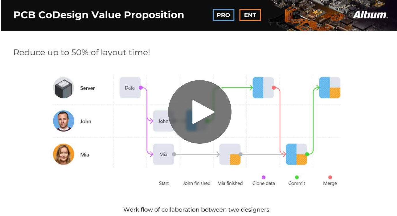
Expand your collaboration skills and stay ahead of the curve with PCB CoDesign. Design teams often grapple with prolonged design cycles and coordination issues, leading to delays and inefficiencies. In the current landscape, design processes are hindered by fragmented collaboration, resulting in increased layout times and difficulties in synchronizing design updates.