Welcome, Guest

Sign in to learn, create, and do more with the product you love.

News & Updates

Filters:
Tag
NEW
Blog
Power Integrity Issues?

Power problems can be hard to spot until it’s too late. See how easy it is to analyze your power nets, check voltage drops, and improve reliability with Power Analyzer by Keysight - all without leaving your design environment.

NEW
Embedded thumbnail for Coming Soon: Solder Mask Zero Expansion
New in Altium Designer 25
Coming Soon: Solder Mask Zero Expansion

Solder Mask Zero Expansion marks a move toward industry alignment, specifically with IPC-7351B and IPC-2581B standards. It changes the default solder mask expansion value from 4 mil to 0 mil. Discover more upcoming updates on our Coming Soon Page.

NEW
Embedded thumbnail for Analog Supply without a Ferrite: Proper Isolation Techniques Explained
How-To's
Analog Supply without a Ferrite: Proper Isolation Techniques Explained

In our new tutorial, you'll learn why ferrite beads may not be the best choice for isolating analog and digital supply pins on integrated circuits. Zach Peterson debunks common misconceptions about ferrite bead isolation and introduces better alternatives, including dedicated LDOs, precision voltage references, and effective filtering techniques to help you achieve cleaner analog signals in your designs.

Blog
Signal Mistakes Are Expensive

See how the Signal Analyzer by Keysight in Altium Designer lets you run signal integrity checks directly within your design environment. Read our article to learn how to effectively manage impedance, return paths, stackups, and more.

Embedded thumbnail for Enhanced Constraint Manager in Altium Designer 25. Part II: Physical Constraints and Routing Differential Pairs
Enhanced Constraint Manager in Altium Designer 25
Enhanced Constraint Manager in Altium Designer 25. Part II: Physical Constraints and Routing Differential Pairs

In the second video of Samer Aldhaher’s "Enhanced Constraint Manager" series, we continue designing a 1 kW, 400 V brushless DC motor driver. This episode focuses on setting physical constraints using constraint sets, routing differential pairs, and demonstrating the Auto Shrinking feature in Altium Designer 25.

Embedded thumbnail for Auto-tuning Your Way to Faster PCB Design
Altium Designer's 25 Quantitative Benefits
Auto-tuning Your Way to Faster PCB Design

Watch how the Auto Tuning feature in Altium Designer 25 delivers optimized DDR4 routing in a single click! Fewer steps, massive time savings. Try our Benefit Calculator to estimate your own time and cost savings.

Blog
Twice the Insight. One Seamless Simulation Bundle

Ensure power and signal integrity with the Keysight Bundle in Altium Designer. Catch issues early, reduce rework, and optimize your PCBs - all within one integrated environment featuring Signal & Power Analyzer.

Embedded thumbnail for Enhanced Constraint Manager in Altium Designer 25. Part I: From Directives to Creepage Rules
Enhanced Constraint Manager in Altium Designer 25
Enhanced Constraint Manager in Altium Designer 25. Part I: From Directives to Creepage Rules

We are introducing a new video series on the Enhanced Constraint Manager in Altium Designer 25. In the first chapter, Samer Aldhaher demonstrates how to define net classes, apply clearance and creepage rules, and validate constraints within both the schematic and PCB. The video uses a 1kW, 400V brushless DC motor driver project to illustrate real-world applications.

Embedded thumbnail for Design Faster with Altium Designer 25
Altium Designer's 25 Quantitative Benefits
Design Faster with Altium Designer 25

Every second and every click count in the product development cycle. See how the new PCB Layout Replication feature in Altium Designer 25 boosts your efficiency in the PCB design process. Want to improve even more? Check out our Benefit Calculator now!

Embedded thumbnail for Creating PCB Drill Drawings and Tables in Altium Designer
How-To's
Creating PCB Drill Drawings and Tables in Altium Designer

If you want to learn more about drill drawings and tables in your PCB designs using Altium Designer, this tutorial is a must-watch. In the video, our Tech Consultant Zach Peterson walks you through multiple methods for generating these critical fabrication documents, including automatic Gerber outputs and custom drawings.

Embedded thumbnail for Streamlining Team Collaboration in Industrial PCB Projects - Recording Preview
New in Altium Designer 25
Streamlining Team Collaboration in Industrial PCB Projects - Recording Preview

This webinar recording shows how Altium Designer and Altium 365 improve team collaboration in industrial PCB projects. It covers features like version control, live commenting, task tracking, and JIRA integration to help teams work more efficiently and reduce costly errors.

Blog
Preparing for Prototype: Final Component Validation

Final component validation is the last critical check before building a prototype, ensuring all parts are accurate, available, and viable. This article shows how Altium’s integrated tools—like SiliconExpert, Z2Data, Octopart, and BOM Portal—help teams avoid costly surprises and prepare with confidence.

Blog
Getting Started with Harness Design in Altium Designer 25

Explore the essential steps and tools for Harness Design in Altium Designer 25, from initial setup to final documentation. The article highlights how the unified design environment streamlines the entire process, improving efficiency and project integration.

Blog
The Future of PCB Design Starts Here

Altium Designer is constantly evolving, with powerful new features and updates on the way. Get an exclusive first look at what’s coming next—visit our Coming Soon page to stay up to date with the latest innovations.

Blog
Simplify Harness-to-System Connections for Better PCB Design Outcomes

Struggling to keep harness and system designs in sync? In our brand-new article we explore how integrating PCB and harness design workflows can eliminate errors, improve collaboration, and accelerate your development process. Discover a smarter approach to connecting your harness to the system.

Embedded thumbnail for AC Coupling Capacitors: Placement for High-Speed PCB Design
How-To's
AC Coupling Capacitors: Placement for High-Speed PCB Design

Learn the facts about AC coupling capacitor placement in high-speed PCB designs. In this video, Zach Peterson explores the ongoing debate: should AC coupling capacitors be placed near the transmitter or the receiver in high-speed differential pairs?

Tag
Blog
DFM/DFA Requirements in Systems Engineering

Learn how integrating DFM and DFA principles into systems engineering ensures manufacturable, cost-effective PCB designs by optimizing CAD, CAM, and requirements management in our new article by Javier Alcina.

Blog
Best Practices for Electronics Project Management - Part 2

Part 2 of this series covers essential project management techniques for electronics design teams. Rafał Stępień discusses effective data organization, revision control, and collaboration strategies to improve efficiency and minimize errors.

Blog
Rigid-Flex PCBs: Understanding the Pros, Cons, and Fabrication Considerations

Read our new article which discusses the advantages of rigid-flex PCBs, such as space-saving designs and enhanced reliability, while also addressing potential challenges in their fabrication. It provides essential design and manufacturing tips to help engineers effectively implement this technology in various applications.

Blog
The Role of Automation & Robotics in Wire Harness Assembly

Our new article highlights how automation and robotics are transforming wire harness assembly, improving efficiency, precision, and cost-effectiveness. Technologies like robotic wire handling and AI-driven testing are paving the way for smarter production. However, challenges like custom designs and high costs still persist.

Blog
Wiring for the Final Frontier: A Guide to Space-Grade Harness Design

Wiring harnesses are mission-critical in space systems, requiring strict adherence to ECSS-Q-ST-70-61C and NASA-STD-8739.4A. In "Wiring for the Final Frontier: A Guide to Space-Grade Harness Design", Kamil Jasiński explores key design principles, material selection, and testing to ensure reliability in extreme environments.

Blog
Ideal Rectifier Bridge

Read Marcin Lewandowski's article explaining how MOSFETs are replacing traditional diodes for reverse polarity protection. Step into the future of energy-efficient electronics!

Blog
Overview of the Gerber X3 File Format

Want to learn how the Gerber X3 file format simplifies data exchange by unifying assembly and fabrication details in a single file? This article explores the format and its role in streamlining PCB manufacturing.

Tag
Embedded thumbnail for How I Improved my Collaboration Efficiency with Altium 365 | Altium 365: Power User Insights
How I Improved my Collaboration Efficiency with Altium 365 | Altium 365: Power User Insights

Collaboration with other teams or contractors in the electronics industry is typically a painful and inefficient experience. All too often, communication is left until the last minute when boards are all but ordered. Let's talk about how to collaborate with colleagues with Altium 365 in a different way.

Embedded thumbnail for Working with Annotation Tools
How to Work with Draftsman
Working with Annotation Tools

Draftsman Documents provide annotation tools to convey physical properties such as tolerances and surface finish

Embedded thumbnail for 3D View Control
How to Work with 3D Mode
3D View Control

Learn how to use the 3D display mode of the PCB and learn to control the camera in this mode in this video

Embedded thumbnail for Impedance Calculation Single-Ended Transmission Lines
Impedance calculation
Impedance Calculation Single-Ended Transmission Lines

Transmission lines help preserve signal integrity and reduce EMI in high speed designs. We’ll show you you to define your single ended transmission lines in Altium Designer and automatically calculate impedance on a two layer and multi-layer board.

Embedded thumbnail for Working with Dimensions: Draftsman Documents
How to Work with Draftsman
Working with Dimensions: Draftsman Documents

Draftsman Documents provide dimensioning tools to capture and display the physical features of the product for fabrication and documentation. 

Embedded thumbnail for Impedance Calculations: Differential Pairs
Impedance calculation
Impedance Calculations: Differential Pairs

Altium designer makes it easy to calculate geometry when you need to calculate impedance for differential pairs. We’ll go over how differential pairs can help with a two layer and multi layer board, as well as what types you can create such as differential co-planar, and how to configure them for your specific design.

Embedded thumbnail for Creating and using templates
How to Work with Draftsman
Creating and using templates

Draftsman Templates are a quick way of laying out your Draftsman Document in Altium Designer. We’ll show you how to utilize them and the differences between sheet and document templates.

Embedded thumbnail for Adding 3D Assemblies to a Multi-Board Project
How to work with Multiboard
Adding 3D Assemblies to a Multi-Board Project

The next step in the multiboard design process is adding 3D PCB Assemblies. We’ll show you how to add them to your design and how to work with the Assembly Editor.

Embedded thumbnail for Altium 365 - Design Collaboration | Tasks
Getting Started with A365
Altium 365 - Design Collaboration | Tasks

The Tasks feature brings lightweight task tracking to further enhance design collaboration in Altium 365. With Tasks, you will never lose an important action item and easily gain a high-level view of the state of your project, all without leaving your design environment. 

Embedded thumbnail for Adding Additional Views in a Draftsman Document
How to Work with Draftsman
Adding Additional Views in a Draftsman Document

If you need additional views in your documentation, Altium Designer’s Draftsman Document editor can help. We’ll show you how to add and configure different views including the component view, the section view, the detail view, the isometric view, variants, the legend for the layer stack, the board region view, and the board realistic view.

Embedded thumbnail for Draftsman Document Views - Fabrication and Drill Drawings
How to Work with Draftsman
Draftsman Document Views - Fabrication and Drill Drawings

The Draftsman Document Editor allows you to add a fabrication view and a drill drawing view to your outjob files. We’ll show you how to get them set up and details you can control from the properties panel.

Embedded thumbnail for Altium 365 - Version Control | Project History
Getting Started with A365
Altium 365 - Version Control | Project History

Project History in a Nutshell: - Presents events in a chronological timeline (Creation, Commits, Releases, Clones, and MCAD Exchanges) - Auto-generates Differences Summary to view the differing entities (e.g., replaced components) - Even a non-expert can act on a revision (Download, View, Revert)

Embedded thumbnail for Resolving Conflicts in Multi-board Schematics
How to work with Multiboard
Resolving Conflicts in Multi-board Schematics

When mismatched pin names in your multi-board schematic cause disconnects and conflicts you can use Altium Designer’s tools to resolve these conflicts. We’ll show you the Connection Manager and the various solutions to solve your connection issues.

Embedded thumbnail for Draftsman Document Board Assembly View
How to Work with Draftsman
Draftsman Document Board Assembly View

The Draftsman Document can include a Board Assembly View. We’ll show you how to add it and the properties you can change to create the exact view or views you need.

Embedded thumbnail for Placing Connections Between Boards
How to work with Multiboard
Placing Connections Between Boards

A multi-board design requires relationships between several board designs referred to as interboard connections. We’ll show you the different types of connections and how to connect your boards using the proper connection type.

Embedded thumbnail for Show the Net Connections Between Select Components
How-To's
Show the Net Connections Between Select Components

This video demonstrates how to show net-specific component connections. This is helpful when routing as you’re able to reduce clutter and focus on the connections on which you are working.

Tag
Integrating Requirements June 2025 Webinar
On-Demand Webinar Mag 28, 2025
Integrating Requirements into Your PCB Design Workflow
Join our webinar where you will learn about integrated requirements tools who can help you eliminate late-stage design changes, AI support through system requirements and integration of design requirements directly in PCB Design. Don't miss it, register now!
Streamlining Team Collaboration
On-Demand Webinar Apr 17, 2025
Streamlining Team Collaboration in Industrial PCB Projects
Join us for our upcoming webinar to discover how Altium Designer and Altium 365 can transform your team’s collaboration and take your PCB design projects to the next level. Attend for a chance to win free access to the Altium 365 Training Bundle.
PCB CoDesign Webinar
On-Demand Webinar Gen 24, 2024
Discover How Altium Designer 24 Revolutionizes Team Dynamics in PCB Design
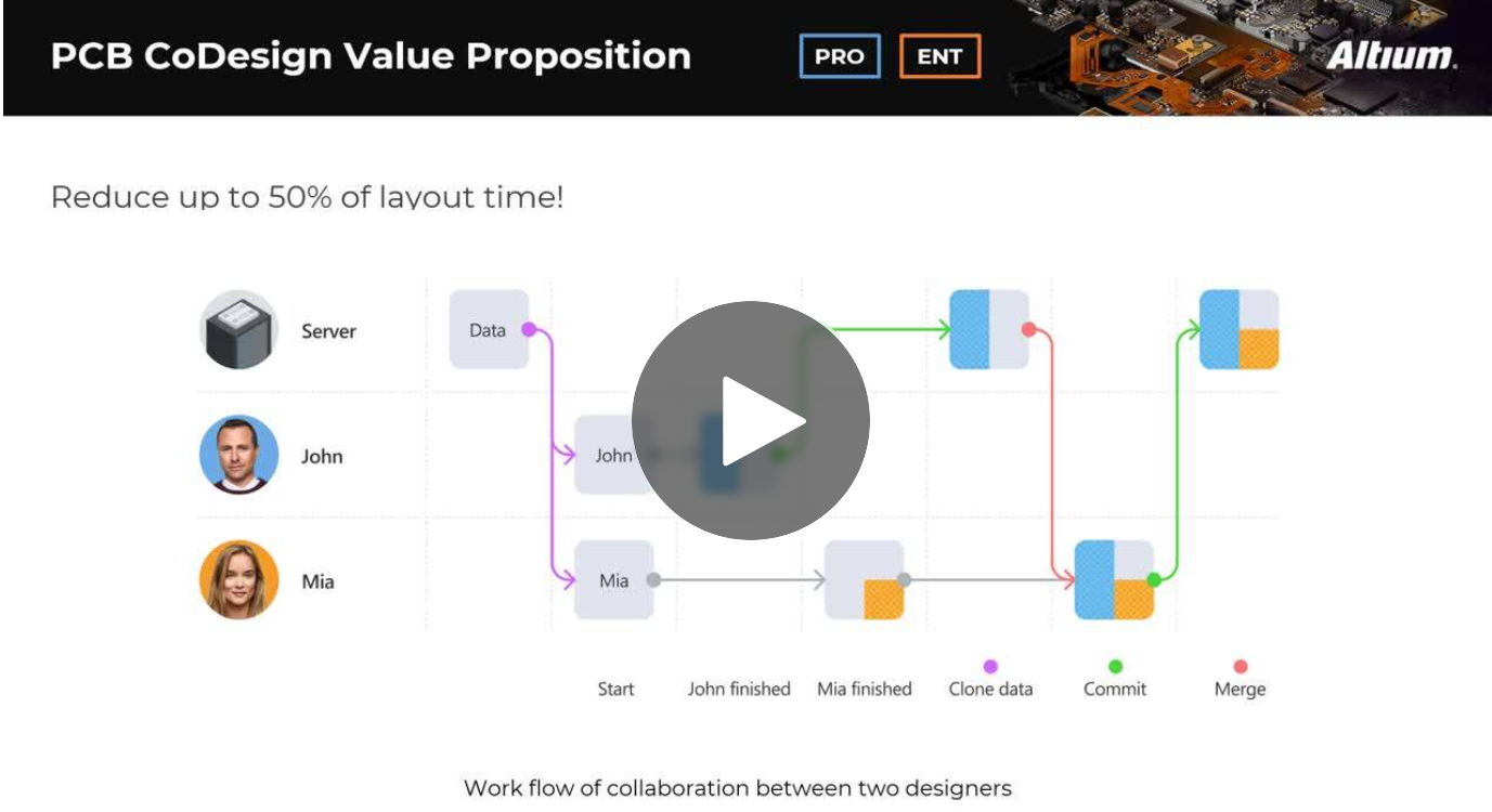
Expand your collaboration skills and stay ahead of the curve with PCB CoDesign. Design teams often grapple with prolonged design cycles and coordination issues, leading to delays and inefficiencies. In the current landscape, design processes are hindered by fragmented collaboration, resulting in increased layout times and difficulties in synchronizing design updates.