News & Updates


Blog
•
Working with Design Variants
The concept of design variants entails taking a single PCB design, and then on the assembly side, modifying specific components used in the design. Either by not installing, not installing, or choosing alternate components as replacements on a specific assembly to ultimately create different end products. In that way, you could support multiple product lines. This article describes the approach to working with variants.

Blog
•
Setting Up Concord Pro Revisions and Lifecycle
Before anything else, some advice. The revisions and lifecycle are an area that takes some planning. It used to be that Concord Pro was primarily for components, but now it has gone far beyond that. With the ability to store and manage many other items, including your various templates, projects, even PDF documents, not everything will have the same revision scheme. Concord Pro is so powerful that it can handle any revision scheme you’d want to set up.


Blog
•
How to Successfully Design a BGA
Whether the board will be placed in a high pressure vessel or underwater, your design will need to withstand pressure to avoid failure. On the enclosure side, your vessel should be rated up to a certain pressure and may require frequent cycling to prevent implosion. On the electronics side, component selection and layout (especially at high voltage) become critical to preventing failure and ensuring reliability.

Blog
•
Altium Designer 20.2 Update 1 is now available
The first update of Altium Designer 20.2 and Altium NEXUS Client 3.2 is now available. You can update through the Altium Designer update system ("Extensions and Updates") or download fresh builds from the Downloads section of the Altium website. Click on "Read More" to see a list of all changes in this update.

Blog
•
How Copper Foil Roughness Affects Your Signals and Impedance
The history of engineering, both electrical and mechanical, is littered with approximations that have fallen by the wayside. These approximations worked well for a time and helped advance technology significantly over the decades. However, any model has limits on its applicability, and the typical RLCG transmission line model and frequency-independent impedance equations are no different. Copper foil roughness modeling and related transmission line impedance simulations are just one of many areas in which standard models cannot correctly treat signal behavior.

Blog
•
What is Burn-in Testing for Electronics?
Once you’re planning for production of any new board, you’ll likely be planning a battery of tests for your new product. These tests often focus on functionality and, for high speed/high frequency boards, signal/power integrity. However, you may intend for your product to operate for an extreme period of time, and you’ll need some data to reliably place a lower limit on your product’s lifetime. In addition to in-circuit tests, functional tests, and possibly mechanical tests, the components and boards themselves can benefit from burn-in testing.
Blog
•
PCB Design for Testability to Ensure High Yield and Quality
If you remember your days in school, then you probably remember the feeling of happiness and celebration when you pass a big exam. You’ll feel the same sense of adulation when your board spin passes a barrage of pre and post assembly tests, but a complex design might not reach that stage unless you implement the right design for testability methods. There are some simple steps that can help your manufacturer identify and quickly implement important bare-board and in-circuit testing (ICT), especially on critical circuit blocks.
Blog
•
Top Tips from Experienced Flex Designers
This article describes the best hints and tips for designers of rigid-flex circuits. These tips include choosing the most appropriate material, suggestions for coordinating the PCB with the manufacturer, and a set of rules to be followed while PCB design.

Blog
•
How Do Capacitor Mounting Structures And Footprints Impact Total Inductance?
There are a number of factors at play when it comes to the impact of inductance on high-frequency power distribution systems. This article will focus on the inductance of the capacitor footprint along with the inductance of vias from the capacitor footprint to the PCB power planes. Included are the various types and sizes of footprints for ceramic capacitors as well as a footprint for a tantalum capacitor; how changing the footprint impacts inductance and test results obtained for different capacitors.
Blog
•
How to Perform Differential Pair Tuning in Altium Designer 20
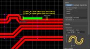
In order to properly suppress common-mode noise, differential pairs must be routed in parallel, with perfect symmetry, and with matched lengths. In real PCBs, meeting these three objectives isn’t always possible. Instead of eyeing out your different pair lengths, the interactive routing tools in Altium Designer make differential pair length matching easy. You can encode permissible length mismatches as design rules as part of controlled impedance routing, or you can manually perform differential pair tuning using a variety of meandering styles. Here’s how this works in Altium Designer.

Blog
•
Driving Haptic Vibration and Feedback in Wearables
Augmented reality, virtual surgery, limb replacements, medical devices, and other new technologies need to incorporate haptic vibration motors and feedback to give the wearer a full sense of how they are interacting with their environment. Unless these cutting-edge applications include haptic vibration and feedback, users are forced to rely on their other four senses to understand the real or virtual environment.

Blog
•
Back Drilling Example in Altium Designer: One of the Easiest Ways to Improve Signal Integrity
Over the last 20 years, electronic devices have become increasingly sophisticated. Less than two decades ago, just having a mobile phone to make calls was rare; today, our phones power our lives. To meet the growing demand for smartphone technology, technology has become faster, more functional, and intuitive. Improvements to the component base have streamlined processes while reducing manufacturing costs.

Blog
•
Is it Simultaneous Switching Noise or Crosstalk?
Going deeper into crosstalk, there is always the issue of verifying EMI/EMC compliance through test and measurement. With the multitude of signal integrity problems that can arise in real PCBs, how can the astute designer distinguish them all? Some problems are clearer than others, with specific signal integrity measurements being developed for testing and measuring particular aspects of signal behavior. The fact is, multiple signal integrity problems could be present on a single interconnect simultaneously.

Blog
•
Sharing PCB Data with Manufacturers in the Cloud
Once you’ve finished your new project and you’re ready to push it to your manufacturer, you’ll normally be stuck in an endless email chain with an engineer, or you’ll have to share cloud links with each other. The cloud sharing and design release tools in Altium Designer and Altium Concord Pro are a huge help in this area. In this post, I’m going to take an existing project I’ve worked with in a number of recent blogs, create some fabrication and assembly documentation, and finally push this data to a manufacturer using Altium Concord Pro.

Blog
•
The Great PCB Layout "Rules of Thumb" Debate Rages On
To this day, I still see many PCB layout “rules of thumb” that first became common nearly 20 years ago. Do these rules still universally apply? The answer is a firm “maybe.” The discussion around PCB layout rules of thumb is not that these rules are correct or incorrect. The problem is that the discussion around these rules often lacks context, leading to the always/never type of discussion seen in some popular forums. My goal in this article is to communicate the context behind the common PCB design rules.

Blog
•
How to Design Your PCB Test Coupon and What You Can Test
As the operating speed of components has increased, controlled impedance is becoming more common in digital, analog, and mixed-signal systems. If the controlled impedance value for an interconnect is incorrect, it can be very difficult to identify this problem during an in-circuit test. However, testing is normally performed on a PCB test coupon, which is manufactured on the same panel as the PCB. If you want to get through board spins quickly and aid future designs, you might consider designing a test coupon and keeping it handy for future designs.


Blog
•
Altium DbLibs and Electronic Components in the Cloud with Altium Designer 20.1
Altium’s DbLib support is one of the oldest and most loved features of Altium Designer for managing electronic components and their data. They’ve been present in the software world since before I could fathom the existence of Ohm’s law. Altium 20.1’s new Component Sync feature allows you to synchronize virtually any database or database Library with Altium 365, taking advantage of both approaches strengths.

Blog
•
Get Ready for WiFi 7 under the 802.11be Standard
Just as WiFi 6 and 6E are starting to hit the market and new chipsets become available, WiFi 7 is in the works under the 802.11be standard. While this technology still has not hit the market, I would expect more inquiries for experimental systems, evaluation modules, and surface-mountable modules to come up once the first chipsets become available. Now is the time to start thinking about these systems, especially if you’re developing evaluation products to support WiFi 7.

Blog
•
What Goes Into Rugged Electronics Design?
Rugged electronics need to take a punch mechanically, but there is more that goes into a rugged system than being able to survive a drop on the pavement. This is as much about enclosure design as it is about component selection and manufacturing choices. Mil-aero designers often use the term “harsh environment” to describe a number of scenarios where an electronic device’s reliability and lifetime will be put to the test. If you want to make your next product truly rugged, it helps to adopt some of their strategies in your PCB layout.

Blog
•
PCB Testing 101: Important Methods and Metrics
There are many quality checks used to ensure a design will be manufacturable at scale and with high quality, but a lot of this can happen in the background without the designer realizing. No matter what level of testing and inspection you need to perform, it’s important to determine the basic test requirements your design must satisfy and communicate these to your manufacturer. If it’s your first time transitioning from prototyping to high-volume production, read our list of PCB testing requirements so that you’ll know what to expect.

Blog
•
Using SDRAM vs. DDR RAM in Your PCB Design
Embedded computers, vision devices, DAQ modules, and much more will all need some memory, whether it’s a Flash chip or a RAM module. Normally, something like a Flash memory chip or a small eMMC module would not be used for temporary storage as the device requires constant rewrites. Instead, if you happen to need a volatile memory solution, you would go for static (SRAM) or dynamic RAM (DRAM). If you need to decide which type of memory to use in your board, keep reading to see some of the basic design guidelines for SDRAM vs. DDR memory modules.

Blog
•
PCB Ground Plane Best Practices in Your Multilayer Stackup
Using a PCB ground plane in a stackup is the first step towards ensuring power and signal integrity, as well as keeping EMI low. However, there are some bad myths about ground planes that seem to persist, and I’ve seen highly experienced designers make some simple mistakes when defining grounds in their PCB layouts. If you’re interested in preventing excess emissions and ensuring signal integrity in your layout, follow these simple guidelines for implementing a PCB ground plane in your next board.

Blog
•
Using an LDO vs. Switching Regulator in Your PCB
As much as we’d like, the power we supply to electronics isn’t always stable. Real power sources contain noise, they might exhibit power instability, or they dropout unexpectedly. Thankfully, we have power regulators to help prevent some of these problems. For low power devices, we generally see two types of power regulators: a low dropout regulator (LDO) or a switching regulator. You can mix and match these at different points along your power bus, but there’s still the matter of choosing whether to use an LDO vs. a switching regulator in your designs.

Blog
•
Using Altium 365 for Sharing Simulations in the Cloud
Post-layout simulators for your PCB are very valuable tools. If you’re working through a complex design, it’s a good idea to put it through some level of simulation and analysis to evaluate the design before manufacturing. This is all easy with the cloud collaboration tools in Altium 365 and Ansys field solvers thanks to the EDB Exporter utility in Altium Designer. These existing tools in Altium Designer and any of the Ansys field solver utilities give you a simplified way to share design data, EDB files, and simulation results with anyone on your design team.

Blog
•
How to Speed Up Your DFM Report Process in the Cloud
Experienced fabricators will tell you: any design could have some hidden DFM problem that will interfere with manufacturability, quality, or yield. Making use of your design rules is just the start of preventing DFM problems, you’ll want to collaborate with your manufacturer throughout the design process if you want to spot and correct DFM problems. Within Altium Designer, there are multiple reports you can generate for your projects that will help you summarize important information on your board for a client or a manufacturer.

Blog
•
The Digital Engineer's Guide to RF PCB Layout and Routing
With modern systems running at higher frequencies, incorporating multiple wireless protocols, and interfacing with many analog sensors, advanced designs require knowledge from digital and RF design disciplines. If you’re now starting to work in the RF realm and you need to design an all-analog or mixed-signal system, RF PCB layout will need to become a new specialty. If you’re a digital designer and you’re now jumping into high-frequency analog design, keep reading to learn more about RF PCB layout and routing.

Blog
•
Microstrip Ground Clearance: How Close is Too Close?
If you take a look at any guidelines for controlled impedance traces, you’ll clearly see that the trace width is calculated without any ground pour near the trace. However, most designers will state that unused areas on each PCB layer should be filled in with grounded copper pour. If you bring some ground pour near a microstrip, you’ve now formed a coplanar waveguide arrangement. So now the question becomes, how much microstrip to ground clearance do you need to ensure you’ve hit your impedance goals?

Blog
•
PCB Layout Guidelines for Switching Power Supplies and Regulators
In this article, I want to briefly focus on how power supplies and regulators are different, although this should already be clear to most designers. For a power supply and for a PCB with an on-board regulator, the switching regulator layout will be a major determinant of overall system performance. Therefore, we’ll largely look at some layout guidelines for switching power supplies in terms of regulator layout.

Blog
•
PCB Sharing and What Data You Can Share in Altium 365
Altium 365 is giving design teams a new way to share and manage their design data. Most users are probably aware of project-level and component-level PCB sharing features, but sharing actually extends down to the level of individual files thanks to the managed content system within Altium 365. If you’ve ever wanted a single place to store and manage all of your design data, then Altium 365 is here to help you and your team stay organized.

Blog
•
How to Combat Power Supply EMI in Your PCB
Power supplies are one of those systems we all tend to take for granted. Everyone’s first task in power supply design is usually to ensure the voltage and current output reach the desired level, probably followed by thermal considerations. However, due to safety issues, EMC requirements, the use of higher PWM frequencies, and the need for smaller packaging, power supply EMI should be a major design consideration. With that being said, what are the major sources of power supply EMI, and how can power supply designers keep them in check?

Blog
•
Leveraging the Free Footprint Community to Design at Lightning Speed
Designing footprints is a job most people hate. It’s tedious, time-consuming, and doesn’t result in much except, well, a footprint. Companies now realize this pain point and offering designers free, well-designed PCB footprints. Why would they spend their time doing this? In this article, we’re going to review some of the free offerings that exist within the PCB design community. Once you’re armed with this information, you will spend most of your time designing and routing boards instead of pulling your hair out creating footprints all day.

Blog
•
Designing for Multiple PCBs in the Same Project
The majority of our PCB designs sit as a single PCB under our Altium Designer projects. It sometimes happens that we have a single project that requires multiple PCBs with various stuffing options, but when it happens, a lot of us tend to get stuck. How do you handle the exact change across both projects? How do you guarantee those changes to be identical? This article will review an approach to managing multiple PCB designs within a single project, ensuring your single source of truth.

Blog
•
Designing 5G Devices
The next stage in the evolution of mobile telephony is here with the roll-out of 5G. The designer looking to incorporate functionality to handle 5G signals into their circuits will face some challenging issues. So, what’s so special about 5G?















Your search returns no results.


