News & Updates
Blog
•
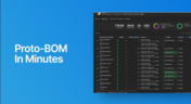
Proto-BOM in Minutes: How BOM Portal Accelerates Component Selection
Still building BOMs the hard way? Discover how modern workflows can help you create a prototype-ready BOM faster while improving visibility into pricing, availability, and risk.


Blog
•
How to Manage Power Integrity and EMI in Complex Multiboard Systems
This article examines the challenges of maintaining power integrity and controlling EMI in complex multiboard systems. It provides practical strategies for managing return paths, connector transitions, and power distribution across interconnected assemblies.

Blog
•
Agile Teams: From Design Tool to Product Development Platform
Learn how Agile Teams evolves beyond traditional PCB design workflows to support connected product development. This webinar explores how centralized data, collaboration tools, and governance capabilities help teams accelerate delivery while maintaining control.

Blog
•
Benefits of Using an Integrated Design Environment for PCB Development
Using separate tools often creates inefficiencies and increases the risk of mistakes. This article explains how integrated design environments streamline workflows by keeping design data connected and accessible.


Blog
•
Enterprise vs. Midsize PCB Design Software: What Actually Changes at Scale
PCB design challenges change significantly as organizations scale. This article explores the key differences between mid-size and enterprise design environments, from collaboration and governance to data management and workflow automation.


Blog
•
BOM Portal vs BOM Tool: What Changes When You Upgrade
Not all BOM solutions work the same way. This article explains the key differences between BOM tools and BOM portals, and why real-time data and collaboration are becoming essential for modern electronics development.


Blog
•
Altium vs KiCAD: Built to Scale From First Board to Full Product
Starting with a simple board today doesn't mean your next project will stay simple. Learn how Altium Designer and KiCAD compare when designs become more complex, teams get larger, and products move toward manufacturing.

Blog
•
Eliminate the Design-to-Production Gap with Agile Teams + Duro
Learn how Agile Teams and Duro connect design and production workflows through a unified system of record. This webinar shows how structured change management and automated data synchronization help teams reduce errors and accelerate product releases.

Blog
•
Agile Hardware Development: How to Scale Speed Without Losing Control
Agile hardware development isn’t just about working faster, it’s about working together in real time. This article explores how shared environments for ECAD, MCAD, sourcing, and requirements management eliminate handoff delays and improve decision-making across teams.


Blog
•
How Reusable Parameters in Requirements Reduce Errors and Speed Up Iterations
Verification becomes much easier when requirements and system performance data stay connected automatically. This article explains how reusable parameters and V&V rules help teams detect violations earlier and validate designs with greater confidence.


Blog
•
Complex Engineering Projects Leverage Multiple ECAD/MCAD Formats
This article explores how modern engineering teams manage complex projects involving multiple ECAD, MCAD, and manufacturing file formats across distributed workflows. It highlights the importance of design authority, disciplined revision control, and bidirectional collaboration to ensure accurate integration between PCBs and mechanical systems.


Blog
•
Avoid Costly Interconnect Errors: Essential Multiboard PCB Layout Strategies for Reliable Designs
Complex multiboard designs demand more than just connecting boards together. They require every interface to work flawlessly under real-world conditions. Discover how better pin assignments, return paths, and mechanical planning can dramatically improve reliability and reduce rework.


Blog
•
Mastering Blind and Buried Vias
Check our compilation of essential resources you'll need to use blind and buried vias successfully in an HDI PCB. In our brand new article, we present the main and most valuable information about this technology, which may not be new but is still highly useful in High-Density Interconnect projects.

Blog
•
Penn Electric Racing Pushes the Envelope with Altium 365
Discover how Penn Electric Racing builds award-winning, fully electric racecars with Altium 365, pushing the boundaries of technology and design.

Blog
•
Make Sure to Clean Your No-Clean Flux
No-clean flux has become popular due to its convenience. Learn more about why this solution is used, why cleaning might still be necessary, and how to remove no-clean flux residues. We will try to dispel all these doubts in this brand new article.

Blog
•
SPICE Simulation Module: How To Use Automated Measurements in Simulations To Save Time and Money in Design Challenges
Simulation of electronic circuits is a key factor in the success of your design. A SPICE circuit simulator may be used to speed up the design analysis. Learn more about how Altium Designer can help you with automated measurements, saving you time and money during the design process.
Blog
•
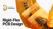
Achieve Seamless Rigid-Flex Design with Altium Designer's Unified Solution
Check out our refreshed feature page about Rigid-Flex PCB Design and see how Altium Designer’s unified environment can help you manage this kind of project with no limitations or additional licensing required.

Blog
•
How to Design a Thermal Prototype PCB
Thermal problems in PCBs often go unnoticed until prototyping, which can be costly. Design teams can't afford endless iterations, but they can conduct lower-cost thermal prototypes. Learn more about this approach in our new article.

Blog
•
6 Challenges of Managing Disconnected PLM Workflows
Discover six challenges of managing disconnected PLM workflows in electronics product development. Identify your main challenge and find the solution here.

Blog
•
DC-Aware Return Current in Mixed Signal PCBs
In this article, we will examine specific cases involving these types of components, where a very low-frequency signal or a DC signal needs to be measured, and the return path must be tracked to ensure the current loop is tight.

Blog
•
PCB Layout Replication: The Perfect Tool for Test Jigs
Replicate your circuits across multiple blocks with just a few clicks using a flawless preview pane, ensuring consistent, perfect results without the need for trial and error. Check out our new article on the PCB Layout Replication feature.

Blog
•
Durability of Pin Plating Materials for PCB Connectors
Pin headers are common components in PCBs, yet one specification often overlooked is the plating material. Discover more about plating materials for electrical connectors in our latest article.

Blog
•
4 Reasons Why We Chose AWS GovCloud (US) for Altium 365 GovCloud
In this blog, we explain the reasons behind our decision to operate Altium 365 GovCloud within AWS GovCloud (US). This partnership is guided by a clear vision: to provide our users with a secure, compliant, and reliable platform for sensitive electronics design data.

Blog
•
How to Reduce Noise From Magnetostriction in Magnetic Components
Magnetic components driven by an AC signal can exhibit an irritating property due to magnetostriction - an effect causing vibrations in magnetic materials, resulting in audible sound. Explore this phenomenon further and discover methods to minimize its impact.

Blog
•
3D MID Design Whitepaper
Dive into a dynamic design experience where you can visualize and edit your circuits in true 3D, offering unparalleled precision. Altium Designer's 3D-MID (Mechatronic Integrated Device) Design tool revolutionizes the design process, providing a fresh perspective. Explore the capabilities and benefits of this feature in our comprehensive guide.

Blog
•
Types of Wiring Harnesses for Electronics
In today's world, many products utilize multiple PCBs interconnected with each other, often leading to a complex network of cables within an enclosure. The most effective way to manage these wires and cables is by constructing a wiring harness. This article explores the various types of harnesses used in electronics.

Blog
•
5 Advantages of Z2Data Integration You Can't Ignore
Z2Data Integration in Altium 365 offers a practical way forward for engineering and procurement. Here are the top five advantages that can streamline your workflows.
Blog
•
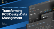
Leveraging Altium Designer's Capabilities: Transforming PCB Design Data Management
Are you curious about how Altium Designer's PLM integration is revolutionizing electronics design? Bid farewell to inefficiencies and expensive revisions, and embark on discovering the cutting-edge approach to managing design data. Dive into our latest article to learn how to leverage this new standard in design data management.


Your search returns no results.


