Welcome, Guest

Sign in to learn, create, and do more with the product you love.

News & Updates

Filters:
Tag
PCB
Live Webinar
Altium Designer Overview
Altium Designer is the #1 PCB design tool for a reason. Join us for this live webinar and get an inside look at Altium’s world-class PCB design solution. See for yourself why design teams around the globe are making the switch to Altium Designer. Register now!
Juni
19
English
12:00 PM, CEST
NEW
Blog
Signal Mistakes Are Expensive

See how the Signal Analyzer by Keysight in Altium Designer lets you run signal integrity checks directly within your design environment. Read our article to learn how to effectively manage impedance, return paths, stackups, and more.

NEW
Embedded thumbnail for Enhanced Constraint Manager in Altium Designer 25. Part II: Physical Constraints and Routing Differential Pairs
Enhanced Constraint Manager in Altium Designer 25
Enhanced Constraint Manager in Altium Designer 25. Part II: Physical Constraints and Routing Differential Pairs

In the second video of Samer Aldhaher’s "Enhanced Constraint Manager" series, we continue designing a 1 kW, 400 V brushless DC motor driver. This episode focuses on setting physical constraints using constraint sets, routing differential pairs, and demonstrating the Auto Shrinking feature in Altium Designer 25.

NEW
Embedded thumbnail for Auto-tuning Your Way to Faster PCB Design
Altium Designer's 25 Quantitative Benefits
Auto-tuning Your Way to Faster PCB Design

Watch how the Auto Tuning feature in Altium Designer 25 delivers optimized DDR4 routing in a single click! Fewer steps, massive time savings. Try our Benefit Calculator to estimate your own time and cost savings.

NEW
Blog
Twice the Insight. One Seamless Simulation Bundle

Ensure power and signal integrity with the Keysight Bundle in Altium Designer. Catch issues early, reduce rework, and optimize your PCBs - all within one integrated environment featuring Signal & Power Analyzer.

Embedded thumbnail for Enhanced Constraint Manager in Altium Designer 25. Part I: From Directives to Creepage Rules
Enhanced Constraint Manager in Altium Designer 25
Enhanced Constraint Manager in Altium Designer 25. Part I: From Directives to Creepage Rules

We are introducing a new video series on the Enhanced Constraint Manager in Altium Designer 25. In the first chapter, Samer Aldhaher demonstrates how to define net classes, apply clearance and creepage rules, and validate constraints within both the schematic and PCB. The video uses a 1kW, 400V brushless DC motor driver project to illustrate real-world applications.

Embedded thumbnail for Design Faster with Altium Designer 25
Altium Designer's 25 Quantitative Benefits
Design Faster with Altium Designer 25

Every second and every click count in the product development cycle. See how the new PCB Layout Replication feature in Altium Designer 25 boosts your efficiency in the PCB design process. Want to improve even more? Check out our Benefit Calculator now!

Embedded thumbnail for Creating PCB Drill Drawings and Tables in Altium Designer
How-To's
Creating PCB Drill Drawings and Tables in Altium Designer

If you want to learn more about drill drawings and tables in your PCB designs using Altium Designer, this tutorial is a must-watch. In the video, our Tech Consultant Zach Peterson walks you through multiple methods for generating these critical fabrication documents, including automatic Gerber outputs and custom drawings.

Embedded thumbnail for Streamlining Team Collaboration in Industrial PCB Projects - Recording Preview
New in Altium Designer 25
Streamlining Team Collaboration in Industrial PCB Projects - Recording Preview

This webinar recording shows how Altium Designer and Altium 365 improve team collaboration in industrial PCB projects. It covers features like version control, live commenting, task tracking, and JIRA integration to help teams work more efficiently and reduce costly errors.

Blog
Preparing for Prototype: Final Component Validation

Final component validation is the last critical check before building a prototype, ensuring all parts are accurate, available, and viable. This article shows how Altium’s integrated tools—like SiliconExpert, Z2Data, Octopart, and BOM Portal—help teams avoid costly surprises and prepare with confidence.

Blog
Getting Started with Harness Design in Altium Designer 25

Explore the essential steps and tools for Harness Design in Altium Designer 25, from initial setup to final documentation. The article highlights how the unified design environment streamlines the entire process, improving efficiency and project integration.

Blog
The Future of PCB Design Starts Here

Altium Designer is constantly evolving, with powerful new features and updates on the way. Get an exclusive first look at what’s coming next—visit our Coming Soon page to stay up to date with the latest innovations.

Blog
Simplify Harness-to-System Connections for Better PCB Design Outcomes

Struggling to keep harness and system designs in sync? In our brand-new article we explore how integrating PCB and harness design workflows can eliminate errors, improve collaboration, and accelerate your development process. Discover a smarter approach to connecting your harness to the system.

Embedded thumbnail for AC Coupling Capacitors: Placement for High-Speed PCB Design
How-To's
AC Coupling Capacitors: Placement for High-Speed PCB Design

Learn the facts about AC coupling capacitor placement in high-speed PCB designs. In this video, Zach Peterson explores the ongoing debate: should AC coupling capacitors be placed near the transmitter or the receiver in high-speed differential pairs?

Embedded thumbnail for Coming Soon: Export 3D-MID Tracks as Centerline Curves
New in Altium Designer 25
Coming Soon: Export 3D-MID Tracks as Centerline Curves

Coming Soon: 3D-MID Track-to-Centerline Export allows you to export conductive tracks on 3D substrates as precise centerline curves within STEP files—enabling seamless integration with advanced 5-axis manufacturing processes. Explore more upcoming upgrades on our Coming Soon page.

Embedded thumbnail for Advanced xSignal and Impedance Control Techniques - Recording Preview
New in Altium Designer 25
Advanced xSignal and Impedance Control Techniques - Recording Preview

This webinar recording explores advanced xSignal and impedance control techniques in Altium Designer 25. It covers defining xSignals, managing impedance profiles, differential pairs, and delay tuning—all essential for high-speed PCB design. Full recording you find here: April 2025 COM Webinar Recording.

Embedded thumbnail for Coming Soon: Embedded 3D Models for Harness Designs
How-To's
Coming Soon: Embedded 3D Models for Harness Designs

Coming soon: the Embedded 3D Models for Harness Designs feature will automatically include Parasolid-format 3D models in your harness layout drawings. This improves integration with MCAD CoDesigner, enabling seamless synchronization between electrical and mechanical design domains. To see more upcoming upgrades, visit our Coming Soon page.

Tag
Altium 365 New Website
Blog
Altium 365 now has its own website!

Discover everything you need to know about Altium 365 and experience our suite of applications for secure, seamless, and streamlined collaboration. Visit now to explore how to streamline your electronic product development.
 

Blog
Altium Designer: Leading the Charge in PCB Design Innovation

In the dynamic field of electronics design, Altium Designer stands out as a pioneer, continuously advancing the boundaries of PCB (Printed Circuit Board) design. Discover the latest innovations in 3D-MID design, high-speed design, and interactive routing in this new article by David Marrakchi.

Blog
What Is Solder Mask Expansion and Which Value Should You Use?

Check out our new article explaining how to ensure sufficient pad area for soldering, manage misregistration tolerance, and maintain proper solder dams between components. It also highlights the role of collaboration with fabrication houses and the use of CAD tools in defining land patterns for advanced electronics designs.

Blog
Pi.MX8 Project - Board Layout Part 3

We continue our exploration of the Pi.MX8 open-source computer module project. In this new installment, we focus on routing planning and then cover all the layers' routing with all the details you need to know if you want to prepare a similar project.

Blog
Mastering Blind and Buried Vias

Check our compilation of essential resources you'll need to use blind and buried vias successfully in an HDI PCB. In our brand new article, we present the main and most valuable information about this technology, which may not be new but is still highly useful in High-Density Interconnect projects.

Blog
Make Sure to Clean Your No-Clean Flux

No-clean flux has become popular due to its convenience. Learn more about why this solution is used, why cleaning might still be necessary, and how to remove no-clean flux residues. We will try to dispel all these doubts in this brand new article.

Blog
How to Design a Thermal Prototype PCB

Thermal problems in PCBs often go unnoticed until prototyping, which can be costly. Design teams can't afford endless iterations, but they can conduct lower-cost thermal prototypes. Learn more about this approach in our new article.

Blog
DC-Aware Return Current in Mixed Signal PCBs

In this article, we will examine specific cases involving these types of components, where a very low-frequency signal or a DC signal needs to be measured, and the return path must be tracked to ensure the current loop is tight.

Blog
PCB Layout Replication: The Perfect Tool for Test Jigs

Replicate your circuits across multiple blocks with just a few clicks using a flawless preview pane, ensuring consistent, perfect results without the need for trial and error. Check out our new article on the PCB Layout Replication feature.

Tag
Embedded thumbnail for Avoid Solder Wicking
DFM and Fabrication Cost/Time Constraints
Avoid Solder Wicking

If solder gets sucked into via holes in can cause an unreliable connection in your otherwise manufacturable design. We’ll show you a few easy ways to avoid this solder wicking using rules.

Display of Alternate Component Parameters
What's New in 22.4
Display of Alternate Component Parameters

Many schematic solutions are created as multivariant. With the new release, the schematic of multivariant project have become even more detailed and informative.

Display of Alternate Component Parameters
What's New in 22.4
备用元件参数显示

很多原理图解决方案均以多变量形式创建。随着新版本的发布,将提供更加详细和翔实的多变量项目原理图。

Components from Altium 365
What's New in 22.4
Components from Altium 365

Working with multiboards has become easier and more convenient. Now you have more component sources at your disposal.

Components from Altium 365
What's New in 22.4
Altium 365 元件

进行多板处理将变得更加轻松、方便。现在可供您使用的元件源将更多。

New Design Reuse Functionality
What's New in 22.4
New Design Reuse Functionality

A reuse bloks help reduce development time and avoid errors. The new Design Reuse Panel and new functionality expands the possibilities for reuse blocks and snippets.

New Design Reuse Functionality
What's New in 22.4
新的设计复用功能

复用块将有助于缩短开发时间并避免错误。新Design Reuse Panel和新功能,扩大了复用块和片段的使用范围。

Embedded thumbnail for MCAD CoDesigner Quick Start: Autodesk Inventor
Working with MCAD CoDesigner extension
MCAD CoDesigner Quick Start: Autodesk Inventor

MCAD CoDesigner is built to address the challenges of electronic product design by enabling seamless collaboration between your electrical and mechanical engineers. This video will show you how to start collaboration between Altium Designer and Autodesk Inventor. 

Embedded thumbnail for Variants in Output Documents
How to work with Variants
Variants in Output Documents

Variants can be used with output files to keep track of all the variations within your design. We’ll show you how to export these files including a Smart PDF, and an outjob file with variants.

Embedded thumbnail for Copper to Edge Clearance
DFM and Fabrication Cost/Time Constraints
Copper to Edge Clearance

It is necessary to maintain edge clearance from your copper in your design. We’ll show you how to maintain it, what exceptions there are to the rule, and how you can ensure its manufacturability.

Embedded thumbnail for Design RF PCB: PCB edge plating
RF PCB Design
Design RF PCB: PCB edge plating

Board edge plating provides additional noise suppression and improves EMC. This video provides some practical tips for creating metalized PCB edges in Altium Designer.

Embedded thumbnail for Using Parameters in Variants
How to work with Variants
Using Parameters in Variants

You can use parameters to change your variants in many ways, such as text and titles. We’ll show you how to alter parameters in the PCB, Schematic, and Draftsman so you can create variants with different parameters.

Embedded thumbnail for How to efficiently use Blankets?
Blankets
How to efficiently use Blankets?

Blanket is a powerful tool for group assignment of properties in schematic documents. It makes it easier and faster to assign circuit classes, differential pairs, and design rules within schematic documents. This video provides instructions on how to use blanket to simplify work in your designs. 

Embedded thumbnail for Query Language: How to Easily Create Expressions
Query Language
Query Language: How to Easily Create Expressions

In this video the main tools which allow to simplify the process of building a query in Altium Designer will be considered. There are several such tools and each of them has its own limitations and peculiarities of use. 

Embedded thumbnail for What to Consider when Designing Edge Connectors
DFM and Fabrication Cost/Time Constraints
What to Consider when Designing Edge Connectors

If your design requires edge connectors there are a few important things to consider. We’ll walk you through how to make sure your design with edge connectors is easy and manufacturable.

Embedded thumbnail for Design RF PCB: Distributed-Element Circuits
RF PCB Design
Design RF PCB: Distributed-Element Circuits

Distributed-element circuits are a topology of a particular shape and size. Filters, power dividers, directional couplers can be built from them. Being calculated in third-party CAD, the topology of such elements can be easily imported into Altium Designer, and we will show you how to do it!

Tag
PCB
Live Webinar
Altium Designer Overview
Altium Designer is the #1 PCB design tool for a reason. Join us for this live webinar and get an inside look at Altium’s world-class PCB design solution. See for yourself why design teams around the globe are making the switch to Altium Designer. Register now!
Juni
19
English
12:00 PM, CEST
Streamlining Team Collaboration
On-Demand Webinar Apr. 17, 2025
Streamlining Team Collaboration in Industrial PCB Projects
Join us for our upcoming webinar to discover how Altium Designer and Altium 365 can transform your team’s collaboration and take your PCB design projects to the next level. Attend for a chance to win free access to the Altium 365 Training Bundle.
PCB CoDesign Webinar
On-Demand Webinar Jan. 24, 2024
Discover How Altium Designer 24 Revolutionizes Team Dynamics in PCB Design
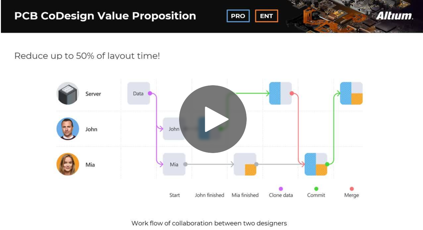
Expand your collaboration skills and stay ahead of the curve with PCB CoDesign. Design teams often grapple with prolonged design cycles and coordination issues, leading to delays and inefficiencies. In the current landscape, design processes are hindered by fragmented collaboration, resulting in increased layout times and difficulties in synchronizing design updates.