News & Updates
NEW
Blog
•
PCB Design Variants: Managing Multiple PCBA Versions
Product variations often require different component populations, alternate parts, or configuration settings while keeping the underlying PCB design unchanged. This article explains how structured variant management keeps these differences organized and ensures each configuration has the correct BOM and manufacturing outputs.
NEW

Blog
•
8 Common DFM Problems PCB Design Rules Catch Before Fab
Preventing DFM problems starts before fabrication not during the fab review. This article covers eight common PCB manufacturing issues and the design rules that help engineers identify and resolve them early.


Blog
•
What is a Multi-CAD Environment? Advantages and Best Practices
Different CAD tools shouldn't mean disconnected teams. Learn how Multi-CAD workflows help engineers review designs, collaborate across disciplines, and catch mechanical or sourcing issues before they become costly redesigns.

Blog
•
Deliver Production-Ready Multiboard PCBs Faster with Manufacturing-Driven Design
This article explores how manufacturing-driven design can help teams validate multiboard products before they reach the factory. It highlights how early checks of interconnects, harnesses, mechanical fit, sourcing, and manufacturing data can reduce late-stage changes and accelerate production readiness.


Blog
•
Stop Chasing Signatures: How Automated Design Sign-offs Accelerate Release Cycles
Automated design sign-offs can eliminate much of the administrative friction surrounding hardware approvals. This article explores how in-context reviews, structured workflows, and automated traceability help teams accelerate release cycles while maintaining control.

Blog
•
Flexible Circuits in Assembly: What PCB Designers Don’t See Until It’s Too Late
Flexible circuits introduce unique assembly challenges that aren't always visible during PCB design, from panel instability and component movement to thermal distortion during reflow. This article explains how design decisions around stiffeners, placement, panelization, and materials can improve assembly yield and reduce costly rework.


Blog
•
Requirements Management Lessons Learned: The S-80 Submarine Program
Fixing one design problem can sometimes create another you didn't see coming. This article uses the S-80 submarine program to show how better requirements traceability can help teams spot hidden impacts before they turn into expensive rework.

Blog
•
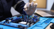
Trust Your BOM: Ensuring Design Data Integrity in Fast-Paced Hardware Projects
A BOM is only valuable if everyone can trust the data it contains. This article shows how connected BOM management helps teams eliminate errors, improve collaboration, and keep fast-moving hardware projects on schedule.

Blog
•
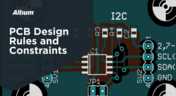
The Best PCB Design Rules System Keeps Your Board Error Free
PCB design rules are the foundation of every successful layout. This article explores how defining and managing constraints helps engineers improve design accuracy, simplify verification, and deliver manufacturing-ready PCBs with confidence.


Blog
•
Why Modern Electronics Teams Are Moving to a Cloud ECAD Platform
Great products are built by connected teams, not disconnected tools. This article shows how cloud ECAD platforms enable real-time co-design, structured design reviews, and seamless collaboration across engineering, manufacturing, and supply chain teams.


Blog
•
Best Practices for Using DNI/DNP Entries in Your PCB BOM
If you’ve ever looked at the BOM for a reference design or an open-source project, you may have seen a comment in some of the entries in your BOM. This comment is either “DNP” or “DNI”. If you think about it, every component placed in the PCB requires some level of placement and routing effort, which takes time and money if you’re working for a client. This begs the question, why would anyone design a board with components they don’t plan to include in the final assembly?

Blog
•
Altium OutJob Files vs. Project Release: What's the Difference?
When it’s time to share your design data with your manufacturer, it’s like taking a leap of faith. Sending off a complete documentation package might seem as easy as placing your fab files in a zip folder, but there are better ways to ensure your manufacturer understands your project and has access to all your design data. For Altium Designer users, there are multiple options for creating and packaging release data into a complete package for your manufacturers.

Blog
•
Testing the Limits of Your LDO's Efficiency
If you’re designing a circuit board to be powered by anything except a bench-top regulated power supply, you’ll need to select a power regulator to place on your board. Just like any other component, your regulator has stated operating specs you’ll see in a product summary, and it has more detailed specs you’ll find in a datasheet. The fine details in your datasheets are easy to overlook, but they are the major factors that determine how your component will interact with the rest of your system.

Blog
•
How Total Harmonic Distortion Affects Your Power System
It would be nice if the power that came from the wall was truly noise-free. Unfortunately, this is not the case, and although a power system can appear to output a clean sine wave, zooming into an oscilloscope trace or using an FFT will tell you a different story. When you take "dirty" power, put it through rectification, and then pass it through a switching regulator, you introduce additional noise into the system that further degrades power quality. If you’re a power supply or power systems designer, then you know the value of supplying your devices with clean, noise-free power.

Blog
•
What PCB Copper Thickness Should You Use?
If you’re an electronics designer or you’re just beginning your career as an engineer, the PCB stackup is probably one of the last things you’ll think about. Simple items like PCB copper thickness and board thickness can get pushed to the back burner, but you’ll need to think about these two points for many applications as not every board will be fabricated on a standard 1.57 mm two-layer PCB

Blog
•
Should You Route Signals in Your PCB Power Plane?
I often get questions from designers asking about things like signal integrity and power integrity, and this most recent question forced me to think about some basic routing practices near planes and copper pour. "Is it okay to route signal traces on the same layer as power planes? I’ve seen some stackup guidelines that suggest this is fine, but no one provides solid advice." Once again, we have a great example of a long-standing design guideline without enough context.

Blog
•
The Anatomy of Your Schematic Netlist, Ports, and Net Names
Electronics schematics form the foundation of your design data, and the rest of your design documents will build off of your schematic. If you’ve ever worked through a design and made changes to the schematic, then you’re probably aware of the synchronization you need to maintain with the PCB layout. At the center of it all is an important set of data about your components: your schematic netlist. What’s important for designers is to know how the netlist defines connections between different components and schematics in a large project.

Blog
•
How to Compare PCB Manufacturing Services for Your Board
There are plenty of PCB manufacturing services you can find online, and they can all start to blend together. If you’re searching for a new service provider, it can be hard to compare all of them and find the best manufacturer that meets your needs. While experienced designers can spot bogus manufacturers from afar, there is always a temptation to go with the lowest priced, supposedly fastest overseas company you can find. However, there is a lot more that should go into choosing a PCB manufacturing service than just price.

Blog
•
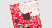
Pi Filter Designs for Power Supplies
Pi Filters are a type of passive filter that gets its name from the arrangement of the three constituent components in the shape of the Greek letter Pi (π). Pi filters can be designed as either low pass or high pass filters, depending on the components used. The low-pass filter used for power supply filtering is formed from an inductor in series between the input and output with two capacitors, one across the input and the other across the output. Keep reading to learn more about their application in the PCB Design.
Blog
•
How to Design a Hybrid PCB Stackup
The first question that should come up when selecting materials and planning a stackup is: what materials are needed and how many layers should be used? Assuming you’ve determined you need a low-loss laminate and you’ve determined your required layer count, it’s time to consider whether you should use a hybrid stackup. There are a few broad situations where you could consider using a hybrid stackup with low-loss laminates in your PCB

Blog
•
Efficient Battery Power Supplies
Batteries offer a great power source for electrical devices that need to be mobile or located somewhere where connection to a mains electricity supply or other power source is impossible. The biggest problem with battery power is the expectation of users that the device will operate for significant periods with the need for recharging or replacing the batteries. This demand is placing the onus on the designer to improve efficiency and reduce power demand to meet this need.

Blog
•
What Target Impedance Should You Use in Your PDN?
A number of us on this blog and in other publications often bring up the concept of target impedance when discussing power integrity in high-speed designs. Some designs will be simple enough that you can take a “set it and forget it” approach to design a functional prototype. For more advanced designs, or if you’re fine-tuning a new board that has existing power integrity problems, target impedance is a real consideration that should be considered in your design.

Blog
•
An Overview of Dual Power Supply Design
Dual power supplies are circuits that generate two different output voltages from a single input source. The simplest method of generating dual output voltages is to use a transformer with two taps on the output winding. Bespoke transformers can have any voltage ratio depending on the number of windings in each part of the output side of the transformer.

Blog
•
Overlapping Planes in Your Mixed-Signal PCB Layout
With digital boards that are nominally running at DC, splitting up a power plane or using multiple power planes is a necessity for routing large currents at standard core/logic levels to digital components. Once you start mixing analog and digital sections into your power layers with multiple nets, it can be difficult to implement clean power in a design if you’re not careful with your layout.

Blog
•
Follow Mixed Signal PCB Design Guidelines With the Best CAD Tools
High-speed digital PCBs are challenging enough to design, but what about mixed-signal boards? Many modern systems contain elements that operate with both digital and analog signaling, and these systems must be designed to ensure signal integrity in both domains. Altium Designer has the layout and signal integrity tools you need to ensure your mixed-signal PCB design does not experience interference and obeys important design standards.

Blog
•
Get Ready for WiFi 7 under the 802.11be Standard
Just as WiFi 6 and 6E are starting to hit the market and new chipsets become available, WiFi 7 is in the works under the 802.11be standard. While this technology still has not hit the market, I would expect more inquiries for experimental systems, evaluation modules, and surface-mountable modules to come up once the first chipsets become available. Now is the time to start thinking about these systems, especially if you’re developing evaluation products to support WiFi 7.



On-Demand Webinar
•
Juni 12, 2025
Proactive Lifecycle Management: Preventing Obsolescence Before It Hits


On-Demand Webinar
•
Apr. 23, 2025
Collaborative Design Review: Ensuring Quality from Schematics to Supply Chain

On-Demand Webinar
•
Apr. 22, 2025
From Prototype to Production: Optimizing BOM Costs Without Compromising Quality with Part Analytics


On-Demand Webinar
•
Apr. 9, 2025
Component Selection in Altium Designer: Making Data-Driven Decisions with Data Integrations
On-Demand Webinar
•
März 25, 2025
Unlocking the full potential of your design team with Altium's enterprise solution

On-Demand Webinar
•
Jan. 24, 2024
Discover How Altium Designer 24 Revolutionizes Team Dynamics in PCB Design


