Welcome, Guest

Sign in to learn, create, and do more with the product you love.

News & Updates

Filters:
Tag
Embedded thumbnail for Altium Training - Design Environment: Opening a Project from a Local Drive
Altium Training
Altium Training - Design Environment: Opening a Project from a Local Drive

Get your PCB design workflow off to a smooth start. This Altium tutorial walks you through opening projects from your local directory - a core skill that keeps your process efficient and organized from day one.

NEW
Blog
Executive Insights Into Electronic Product Development Gaps You Need To Close

Electronics hardware development is falling behind broader product development disciplines due to fragmented workflows, poor collaboration, and limited compliance visibility. This gap introduces risk, delays, and missed opportunities but executives see real business value in modernizing electronics development through better integration, traceability, and lifecycle visibility.

Blog
Sourcing For High-Mix Low-Volume Electronics Manufacturing

High-mix, low-volume (HMLV) electronics manufacturing requires agile sourcing strategies to handle shifting BOMs, erratic lead times, and component volatility. All while controlling costs and ensuring compliance. Cloud-based tools like Altium provide real-time component visibility, BOM collaboration, and supplier integrations to help navigate HMLV complexities.

Embedded thumbnail for What Makes a Great PCB Design Review Submission?
How-To's
What Makes a Great PCB Design Review Submission?

Turn your PCB designs into professional-grade submissions. At Altium, we reveal the key practices that transform schematics, layouts, and documentation into review-ready work that stands out. Watch our brand-new tutorial and take your PCB design process to the next level.

NEW
Embedded thumbnail for Altium Essentials: Design Environment
Altium Training
Altium Essentials: Design Environment

Take control of your PCB design workflow with Altium Essentials: Design Environment. This tutorial module guides you through the fundamentals of workspace management, from handling panels and documents to mastering menus, context commands, and time-saving shortcuts.

Embedded thumbnail for Altium Training - Workspace Folder Structure: Opening the Explorer Panel
Altium Training
Altium Training - Workspace Folder Structure: Opening the Explorer Panel

Discover the key ways to access the Explorer panel in Altium Designer with this step-by-step tutorial. The video walks you through four different methods, giving you the freedom to choose the approach that best fits your workflow.

Blog
One Vision, Three Powerful Solutions: Introducing Altium Discover, Altium Develop, and Altium Agile

We are excited to announce the launch of three new platform-based solutions that will transform the way electronic products are designed, built, and delivered: Altium Discover, Altium Develop, and Altium Agile. These solutions are designed to simplify processes, accelerate innovation, and make collaboration seamless across the entire electronics lifecycle. Together, they realize the purpose of Altium and Renesas: To Make Our Lives Easier.

Embedded thumbnail for Altium Essentials: Workspace Folder Structure Overview
Altium Training
Altium Essentials: Workspace Folder Structure Overview

Altium Essentials: Workspace Folder Structure is a tutorial series designed for PCB designers who are learning the fundamentals of navigating an Altium workspace. This playlist walks through key Explorer panel skills, including multiple ways to open it (via keyboard shortcuts, menus, panel buttons, and workspaces), navigating projects, and understanding the panel’s six core information areas.

Blog
The Top 5 Workflow Bottlenecks Slowing Down Mechanical Engineering Teams

Mechanical engineering teams frequently encounter delays from fragmented communication, disconnected toolchains, and inefficient synchronization processes. This article examines five critical workflow bottlenecks and highlights how ECAD-MCAD integration with real-time, bidirectional updates can eliminate rework and accelerate design iterations.

Embedded thumbnail for NFC Reader Project Part One: Schematics to PCB in Altium
How-To's
NFC Reader Project Part One: Schematics to PCB in Altium

Check out our new, in-depth NFC Reader Project tutorial! In this two-part video series, we design an ESP32-based NFC transceiver board from schematics to PCB layout. In Part 1, we dive into the TRF7970A NFC chip from Texas Instruments and guide you step-by-step through the complete design process in Altium.

Embedded thumbnail for HDI PCB Design Review: nRF52840 Via Sizing & Stack-Up Best Practices
How-To's
HDI PCB Design Review: nRF52840 Via Sizing & Stack-Up Best Practices

Explore key HDI design strategies, from calculating aspect ratios and optimizing pad diameters to managing drill tolerances and refining stack-ups for improved signal integrity. This comprehensive review highlights practical solutions to common HDI challenges, including via-in-pad layouts, clearance violations, and layer thickness adjustments for both mechanical and laser drilling processes.

Embedded thumbnail for 13 Common PCB Problems & How to Fix Them in Altium
How-To's
13 Common PCB Problems & How to Fix Them in Altium

Stop wasting time on manufacturing rework. This guide shows you how to set up Altium’s design rules to prevent the 13 PCB issues that most often derail production ensuring your boards are built right the first time.

Blog
Building a Model Context Protocol Server for Arduinos

This guide walks you through creating an MCP server that turns AI interactions with Arduino into a predictable, automated process handling tasks like board listing, compilation, and serial communication via a fast, menu‑driven interface. Skip the guesswork of prompt nudging and reduce the risk of unintended device issues.

Embedded thumbnail for What's Inside Your MCU Module?
How-To's
What's Inside Your MCU Module?

Are you curious about what’s inside a microcontroller module? Join us as we take a closer look at the Texas Instruments CC3235 Wi-Fi module under the microscope. In this video, we’ll explore its key components, including the microcontroller, flash memory, and RF circuitry, and explain how they work together to power the module.

Tag
Oscilloscope
Blog
The Mysterious 50 Ohm Impedance: Where It Came From and Why We Use It

When we talk about S-parameters, impedance matching, transmission lines, and other fundamental concepts in RF/high-speed PCB design, the concept of 50 Ohm impedance comes up over and over. Look through signaling standards, component datasheets, application notes, and design guidelines on the internet; this is one impedance value that comes up repeatedly. So where did the 50 Ohm impedance standard come from and why is it important?

Camera in water
Blog
Keeping Your Circuits Dry

For the home hobbyist, protecting their electrical devices usually means keeping the coffee cup or soda can away from anything that carries a large voltage. Good practice indicates that electrical devices should be housed in an enclosure to protect expensive components and reduce the risk of electric shocks from exposed circuitry. However, what do you do if the fantastic new device you’ve designed needs to work in a humid, damp, or dripping wet environment? 

PCB with old components
Blog
Tips for Updating Old PCB Designs with New Parts

Have you ever opened up an old design and wondered how much of it was still usable? Maybe you were contacted by an old client, and they want you to provide some updates on an old design. No matter what the situation is, there are times where updating old PCB designs with new parts makes sense. If done correctly and when armed with all the right information up front, you can cut down the total design time while preserving the best parts of your design in a new iteration. Here’s what you can do to update your old designs successfully and how your PCB design features can help.

Design correction
Blog
How to Involve Customers in PCB Product Development

The more complex the product gets, the more involved your customer will need to be to ensure you’re designing to their requirements. When you’re using a data sharing system that integrates with your PCB design tools, it’s easy to give your customers visibility into the product development process. Altium 365 is the only system that integrates with Altium Designer® and gives you the ability to give anyone access to your PCB projects, including your customers and manufacturer.

A man with tablet
Blog
Managing PCB Manufacturing Quality Control in the Cloud

Anytime you’re looking for a fabricator to produce your new design, you should ensure they have a robust quality control program. Where can quality defects arise and how can manufacturers quickly get this information back to a design team? Sometimes emails can leave too much ambiguity and it is difficult to track progress on specific design changes in the PCB layout. If you’re planning to put a new design into high volume production, there are some basic points that should be checked during fabrication and assembly as part of a PCB manufacturing quality control program.

Connector routing
Blog
Controlling Crosstalk In Connector Pinouts

Controlling crosstalk is one of the key goals in any PCB design. In most instances, when we talk about crosstalk, it’s in reference to the unwanted interaction of the electromagnetic field traveling on one transmission line with a neighboring transmission line. But crosstalk can also occur in the connector pin out. This article will describe this type of crosstalk, the types of disruptions it causes, wherein the design cycle it needs to be factored in and how it can be successfully controlled.

History
Blog
What You Can Track in Your Altium Project History

When you’re working through a new PCB design project, and you need to keep track of your project revisions, Altium 365™ creates the ideal environment for collaborative PCB design and revision tracking. Once you upload your projects onto the cloud through the Altium 365 platform, Altium 365 creates a Git repository for your project. It allows you to make it available to collaborators through Altium Designer®. This includes a complete project history, which can be easily accessed by collaborators working on a complex project.

Quickly Compare Gerbers PCB
Blog
Gerber Compare in Altium 365's Online Platform

The moment you push your Gerbers to a manufacturer for a DFM inspection, it can be a nerve-wracking experience waiting for a response. Before you receive your working boards, there will likely be some back-and-forth communication before your board hits the fabrication line. When manufacturers and designers need to resolve problems in Gerber files before fabrication, it helps to have a Gerber compare utility. The newest version of Altium Designer now offers this feature through the Altium 365 platform, giving everyone visibility into changes to Gerbers before fabrication.

Electric car charging
Blog
California Bets on Electric Cars and Plans to Ban Gasoline Car Sales by 2035

No matter how you might feel about renewable energy and associated environmental issues, electric vehicles are becoming more mainstream and will become the primary mode of transportation in the future. For the engineering community, what’s much more interesting is how our power distribution and management infrastructure can support this shift to massive increases in the use of electricity on the grid. So what’s the rub for PCB designers?

BGA Chip
Blog
My Favorite Altium Designer Keyboard Shortcuts and Viewing Features

When you’re working through a complex PCB layout, it always helps to know the shortcuts you can use to stay productive. Altium Designer® keyboard shortcuts, and keyboard + mouse shortcuts, can help you easily walk through your PCB layout during design and as part of final checks during a design review. Here are some of my favorite keyboard shortcuts and viewing options that help me stay productive, and I hope they can do the same for you.

High-speed route
Blog
The IEEE P370 Standard for High Speed PCB Interconnects

High speed PCB interconnects have continued to remain an active challenge in modeling and simulation, particularly when dealing with broadband signals. The IEEE P370 standard is a step towards addressing the challenges faced by many designers in determining broadband S-parameters for high speed structures up to 50 GHz. Although this standard has been in the works since 2015, it finally passed board approval and appears as an active draft standard.

Memory stick
Blog
Class-D Amplifier Design and PCB Layout

Amplifiers can come in all shapes and sizes, depending on their bandwidth, power consumption, and many other factors. A Class-D amplifier design is normally used with high fidelity audio systems, and circuits for a Class-D amplifier are not too difficult to build in a schematic. If you’ve never worked with a Class-D amplifier or you’re looking for a fun audio project, follow along with this PCB layout.

RAM text
Blog
DDR5 vs. DDR6: Here's What to Expect in RAM Modules

Modern digital systems throw the digital electronics textbooks out the window, and high-speed DDR memories are a perfect example of the paradigm shift that occurs when you jump into IC and PCB design. With DDR5 still being finalized, and DDR6 now being discussed, designers who are already comfortable with DDR4 will need to consider how their design practices should adjust to accommodate the constant doubling of data speeds in these high-speed memory technologies.

Explaining the Impedance of the Crystal
Blog
Making the Most of Your Crystal Oscillator

In my experience, the somewhat vague information you might find in a typical crystal datasheet doesn’t enable an engineer to be wholly confident that their design expectations can be met. On the other hand, “blindly” adopting what the crystal datasheet says usually results in adequate frequency stability. If you want to get inside and uncover what is going on, you need to start thinking about the crystal as a phase-shifting network.

Routed PCB
Blog
How Antipads Affect Signal Integrity in Your Multilayer PCB

Antipads on vias and landing pads are a point of contention in modern PCB design, and the debate around the use of these elements in a multilayer PCB is framed as a binary choice. Like thermal reliefs, ground plane splits, and orthogonal routing, the debate around antipads on landing pads and vias is framed as an always/never choice. With today’s modern PCBs, it pays to understand the effects of antipads on signal integrity.

PCB with RF elements
Blog
How to Design a Microstrip to Waveguide Transition

RF structures can be complicated to design and layout, particularly because many RF systems lead double lives as digital systems. Getting an analog signal out of a component and into a waveguide for high isolation routing is not so simple as placing a microstrip or stripline coming off your source component. Instead, you need to create a special microstrip to waveguide transition structure to ensure strong coupling into and out of your waveguide.

Tag
Embedded thumbnail for Setting the Transparency for Layers and Primitives
How-To's
Setting the Transparency for Layers and Primitives

Customize your workspace by setting the transparency of layers and primitives in the PCB.

Embedded thumbnail for Create New Via Types Using the Layer Stack Manager
How to work with Layer Stack Manager
Create New Via Types Using the Layer Stack Manager

In this video, we will learn how to create new via types using the Layer Stack Manager, and how to create new Routing Via design rules using the PCB Rules and Constraints Editor. We will also explore how to use the different types of Via during interactive routing.

Embedded thumbnail for How to Create a Copper Board Report
How-To's
How to Create a Copper Board Report

This video will show how to create a copper board report in your PCB which can be useful for copper balance in DFM process

Embedded thumbnail for Stackup Creation and editing
How to work with Layer Stack Manager
Stackup Creation and editing

This video shows how to view and edit the PCB Layer Stack, select materials and add new layers

Embedded thumbnail for Configuring Your PCB Library
How to create a PCB Footprint
Configuring Your PCB Library

It is important to have accurate footprints to manufacture your PCB. Learn how to configure your PCB library to facilitate footprint creation.

Global parameters
What's New in 22.6
Quick Browsing of Parameters for a Board

Parametric information for your board is now conveniently available from the Properties panel. A single, convenient location with which to browse system, calculated and user-defined parameters, and place as needed in the form of special strings.

Global parameters
What's New in 22.6
电路板参数的快速浏览

您现在可以从Properties面板中轻松获得电路板的参数信息。可以在一个方便的位置,浏览系统、计算和用户定义参数,并根据需要以特殊字符串的形式进行放置。

Embedded thumbnail for How to Validate Links Between Components and Footprints
How-To's
How to Validate Links Between Components and Footprints

Before importing or updating data from the circuit to the board, you must first verify that all components of the circuit are associated with Footprint. Watch this video to learn how to validate the links between your schematic components and footprints.

Embedded thumbnail for How to use Copy Room Format
How to work with Rooms
How to use Copy Room Format

Rooms allow you to use rules on specific areas of your design. This helps immensely with properly defining trace widths and hole sizes for specific components. We’ll show you how easy it is to assign rules to specific rooms in the PCB.

Embedded thumbnail for How To Do Versioning And Releases by Robert Feranec and Michal Faruga
Discovering Altium 365
How To Do Versioning And Releases by Robert Feranec and Michal Faruga

Meet Robert Feranec in an educational video on version control, project history, comments, comparison and other features in Altium Designer 

Active Links in Text
What's New in 22.6
Active Links in Text

You can now specify active links to components and nets within a text frame object on a schematic. This handy navigation aid makes it much easier not only to read the document, but also to work with it.

Active Links in Text
What's New in 22.6
文本中的活动链接

您现在可以在原理图上的文本框对象中,指定指向元件和网络的活动链接。使用此导航辅助工具,即可轻松读取和处理文档。

Multifunctional Pins
What's New in 22.6
Multifunctional pins

You will often see that modern ICs consist of multi-functional pins. In this latest version of Altium Designer it has become far easier and much more convenient to work with such components.

Multifunctional Pins
What's New in 22.6
多功能引脚

常见的现代IC均由多功能引脚组成。在最新版Altium Designer中,我们能够更加轻松、方便地处理此类元件。

Embedded thumbnail for Using Rooms in Rules
How to work with Rooms
Using Rooms in Rules

Rooms allow you to use rules on specific areas of your design. This helps immensely with properly defining trace widths and hole sizes for specific components. We’ll show you how easy it is to assign rules to specific rooms in the PCB.

Embedded thumbnail for Creating a Schematic Symbol: Dealing with Power Pins
How to create a Schematic Symbol
Creating a Schematic Symbol: Dealing with Power Pins

Multiple schematic symbols often require the use of multiple power and ground pins. We’ll show you the difference between hidden and visible power pins, and the various methods you can use to use them in your design however it works best for you.

Tag
Integrating Requirements June 2025 Webinar
On-Demand Webinar Mai 28, 2025
Integrating Requirements into Your PCB Design Workflow
Join our webinar where you will learn about integrated requirements tools who can help you eliminate late-stage design changes, AI support through system requirements and integration of design requirements directly in PCB Design. Don't miss it, register now!
Streamlining Team Collaboration
On-Demand Webinar Apr. 17, 2025
Streamlining Team Collaboration in Industrial PCB Projects
Join us for our upcoming webinar to discover how Altium Designer and Altium 365 can transform your team’s collaboration and take your PCB design projects to the next level. Attend for a chance to win free access to the Altium 365 Training Bundle.
PCB CoDesign Webinar
On-Demand Webinar Jan. 24, 2024
Discover How Altium Designer 24 Revolutionizes Team Dynamics in PCB Design
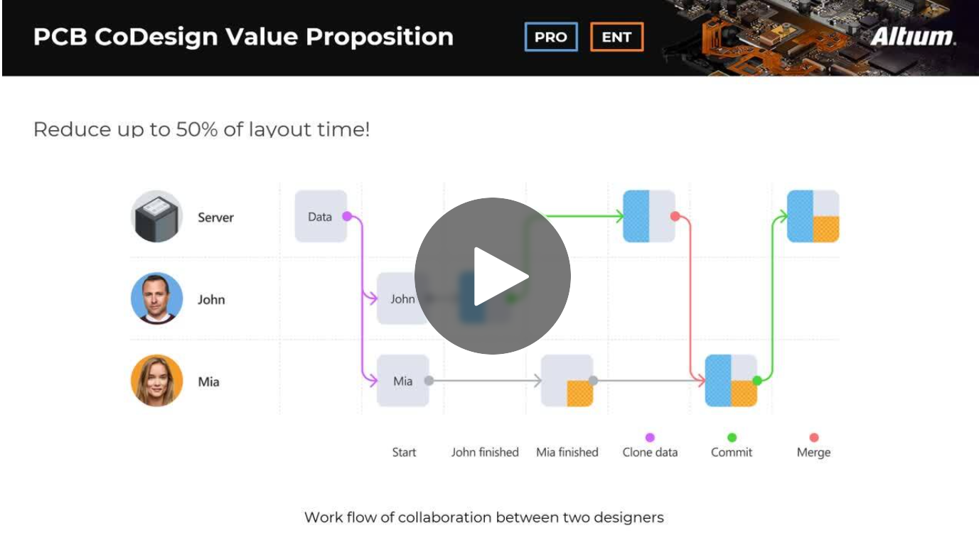
Expand your collaboration skills and stay ahead of the curve with PCB CoDesign. Design teams often grapple with prolonged design cycles and coordination issues, leading to delays and inefficiencies. In the current landscape, design processes are hindered by fragmented collaboration, resulting in increased layout times and difficulties in synchronizing design updates.