Welcome, Guest

Sign in to learn, create, and do more with the product you love.

News & Updates

Filters:
Tag
NEW
Blog
Getting Started with the GreenPAK Introduction Kit

Take your first steps into mixed-signal design with the Renesas GreenPAK Introduction Kit. Ari Mahpour shows how to design, simulate, and validate a clock divider project, making it easy for beginners to start experimenting with programmable mixed-signal devices.

NEW
Embedded thumbnail for Arduino to Custom PCB: Professional Design Transformation
How-To's
Arduino to Custom PCB: Professional Design Transformation

Discover how to upgrade your Arduino Nano-based PCB design into a professional, custom PCB. This tutorial walks through the process of replacing development boards with individual components to create a production-ready design, using a real drone project as the example.

NEW
Blog
Smarter Electronic Part Sourcing for Automotive Purchasing Professionals

Targeted at procurement professionals in the automotive industry, the article outlines the evolving pressures of sourcing components for electrified and connected vehicles. It highlights Octopart’s ecosystem as a unified tool that centralizes availability, compliance, pricing, and lifecycle intelligence to optimize sourcing efficiency.

NEW
Embedded thumbnail for PCB Library Management: One Library or Many?
How-To's
PCB Library Management: One Library or Many?

This detailed guide walks you through the pros and cons of each approach and offers proven strategies for managing component data, whether you're an independent designer or overseeing libraries for an entire organization.

Blog
Stack-Up to Success: Avoid the Pitfalls

"Stack‑Up to Success" highlights how a carefully planned PCB stack‑up is foundational to preventing warpage, managing impedance, and avoiding manufacturing delays by clearly communicating layer construction, materials, and tolerance requirements to fabricators.

Embedded thumbnail for Coming Soon: Sawtooth Rounding Support for Length Tuning
New in Altium Designer 25
Coming Soon: Sawtooth Rounding Support for Length Tuning

Sawtooth Rounding for Length Tuning improves signal‑path accuracy by applying controlled corner‑rounding to sawtooth geometries during both Interactive Length Tuning and within‑pair matching in the Auto Tuning engine. Discover this capability and additional innovations on our Coming Soon page.

Embedded thumbnail for Coming Soon: Z-Axis Clearance Rule
New in Altium Designer 25
Coming Soon: Z-Axis Clearance Rule

The Z-Axis Clearance Rule checks the shortest distance between copper features on different layers in a PCB design. It is available in both the Constraint Manager and the legacy PCB Rules Editor. Discover more new features in Altium on our Coming Soon Page.

Embedded thumbnail for Coming Soon: Advanced Polygon Pour Engine
New in Altium Designer 25
Coming Soon: Advanced Polygon Pour Engine

Now supports true arcs instead of approximated curves in copper pours. This enhanced engine marks a major advancement in the polygon pour process in Altium Designer, delivering smoother and more accurate copper shapes. Native arc rendering improves visual quality and helps ensure cleaner, more professional PCB designs.

Embedded thumbnail for How to Design Rigid-Flex PCB Stackups from Scratch
How-To's
How to Design Rigid-Flex PCB Stackups from Scratch

Watch this tutorial to learn the fundamentals of Rigid-Flex design. We cover everything from understanding polyimide materials and adhesive layers to building complex, multi-layer Rigid-Flex constructions that are ready for manufacturing.

Blog
How to Effectively Use Jira for Hardware Development Projects

Originally built for software development, Jira has become a popular tool for agile project management across various industries. Our new article explores how hardware teams can leverage core Jira features and adapt agile principles to suit the unique needs of hardware development.

Embedded thumbnail for How to Draw Antipads - Complete Tutorial
How-To's
How to Draw Antipads - Complete Tutorial

Discover how to draw and define antipads in Altium with this complete tutorial. Learn three different methods for creating antipads around vias. From simple design rules to advanced polygon cutouts for both basic and complex PCB designs.

Embedded thumbnail for Do PCB Manufacturers Actually Look at Fabrication Drawings?
How-To's
Do PCB Manufacturers Actually Look at Fabrication Drawings?

Explore this in-depth tutorial featuring real fabrication drawings, stackup specifications, and drill tables - all created using Altium Designer’s Draftsman tool. Learn essential insights into PCB data management and manufacturing requirements from an industry perspective.

Embedded thumbnail for Compensating Transmission Line Losses in a PCB Calculator
How-To's
Compensating Transmission Line Losses in a PCB Calculator

This tutorial uncovers the key difference between ideal, lossless impedance calculations and real-world signal behavior giving you practical techniques to design controlled impedance PCBs that deliver reliable performance.

Blog
How to Make Your PCB Layout AOI and X-Ray Friendly

Designing for inspection is key to reliable manufacturing. This article covers practical PCB layout tips to optimize your board for AOI and X-ray inspection helping you reduce defects, false positives, and production delays.

Embedded thumbnail for How Close Can You Bring a Reference Plane?
How-To's
How Close Can You Bring a Reference Plane?

Explore our in-depth investigation into practical simulations using both Altium Designer and Polar Si9000. We demonstrate impedance sensitivity analysis and reveal the real limitations of optimizing reference plane proximity for improved signal shielding.

Tag
Blog
Signal Mistakes Are Expensive

See how the Signal Analyzer by Keysight in Altium Designer lets you run signal integrity checks directly within your design environment. Read our article to learn how to effectively manage impedance, return paths, stackups, and more.

Blog
Twice the Insight. One Seamless Simulation Bundle

Ensure power and signal integrity with the Keysight Bundle in Altium Designer. Catch issues early, reduce rework, and optimize your PCBs - all within one integrated environment featuring Signal & Power Analyzer.

Blog
Preparing for Prototype: Final Component Validation

Final component validation is the last critical check before building a prototype, ensuring all parts are accurate, available, and viable. This article shows how Altium’s integrated tools—like SiliconExpert, Z2Data, Octopart, and BOM Portal—help teams avoid costly surprises and prepare with confidence.

Blog
Getting Started with Harness Design in Altium Designer 25

Explore the essential steps and tools for Harness Design in Altium Designer 25, from initial setup to final documentation. The article highlights how the unified design environment streamlines the entire process, improving efficiency and project integration.

Blog
The Future of PCB Design Starts Here

Altium Designer is constantly evolving, with powerful new features and updates on the way. Get an exclusive first look at what’s coming next—visit our Coming Soon page to stay up to date with the latest innovations.

Blog
Simplify Harness-to-System Connections for Better PCB Design Outcomes

Struggling to keep harness and system designs in sync? In our brand-new article we explore how integrating PCB and harness design workflows can eliminate errors, improve collaboration, and accelerate your development process. Discover a smarter approach to connecting your harness to the system.

Blog
Printed Electronics: The Future of Flexible and Cost-Effective Circuit Design

This article explores the rise of printed electronics as a lightweight, flexible, and cost-effective alternative to traditional PCB design. It highlights key benefits like reduced manufacturing costs, sustainability, and new design possibilities—especially in wearables, medical devices, and automotive applications. 

Blog
New Routing Possibilities with Ultra HDI

Explore how Ultra HDI technology is redefining PCB design. This article breaks down the benefits and manufacturing considerations of Ultra HDI, and how it enables next-level routing density and miniaturization in advanced electronics.

Blog
3D-MID in Focus: Principles, Processes, and Practical Use

This article introduces 3D-MID (Mechatronic Integrated Devices), a technology that integrates circuitry into 3D plastic structures to reduce size, weight, and complexity. It explains the production process, use cases, and benefits of 3D-MID in sectors like automotive, medical, and consumer electronics.

Blog
Eliminate EMI and Signal Integrity Issues in Multi-Board PCB Designs

Ensure signal integrity and minimize EMI in complex electronics. Our new article explains how to address electromagnetic interference and signal integrity challenges in multi-board PCB designs, offering practical strategies and layout considerations for reliable system performance.

Tag
Embedded thumbnail for How to Use a Courtyard Layer for the Component Boundary
How-To's
How to Use a Courtyard Layer for the Component Boundary

In this video, you will see how to use the courtyard layer as a component boundary.

Embedded thumbnail for Creating High-speed Signal Classes with xSignals
How To Work with High-Speed Projects
Creating High-speed Signal Classes with xSignals

You can create, configure, and utilize xSignals in Altium Designer to make your design process more efficient and effective. We’ll show you how to do it manually, using the more comprehensive Create xSignals command, and using the xSignal wizard.

Embedded thumbnail for MCAD CoDesigner Overview
Working with MCAD CoDesigner extension
MCAD CoDesigner Overview

The MCAD CoDesigner in Altium Designer allows for seamless design transfer between the Electrical and Mechanical designers. In this overview, we’ll show you how to transfer from Altium Designer to your CAD tool of choice, then how to resize the board, add mounting holes, add a new connector, and update the board design in Altium Designer.

Embedded thumbnail for Bringing an MCAD Enclosure to ECAD
Working with MCAD CoDesigner extension
Bringing an MCAD Enclosure to ECAD

The Altium Designer MCAD CoDesigner panel and extension make it easy to move a 3D enclosure model from your MCAD tool to Altium Designer. We'll show you how and what to watch out for while your transferring your enclosure model to Altium Designer.

Embedded thumbnail for How to Perform a Component Search in Concord Pro - Altium Academy
How-To's
How to Perform a Component Search in Concord Pro - Altium Academy

In this video, I'll show you how to perform a component search in the Components Panel. Learn how to perform a component search in the Components Panel while using Altium Concord Pro to effectively host all your component libraries from Altium Designer. You can always locate any particular component using this library navigation and place it on your schematic with pricing information from global suppliers. This availability and pricing information gets updated daily directly from the suppliers so you will always get fresh, up to date information. 

Embedded thumbnail for Snapping When Creating Polygons
How to use Snapping
Snapping When Creating Polygons

When creating polygons you can use snap points to form fit your polygons to the exact size and shape you need. We’ll show you how to set your snap points, which ones are most helpful for creating polygons, and how to use the same techniques to create keep out and solder mask areas.

Embedded thumbnail for Automatic Symbol Creation in Altium 365
Library Managment
Automatic Symbol Creation in Altium 365

In order to design your projects, you’ll need a set of components to work with. Although the integration of Octopart with Altium Designer gives us a large repertoire of components, you simply can’t have access to every component model in the world. We’re going to create a component in the Altium 365 workspace with the Symbol Creation Wizard.

Embedded thumbnail for Creating Differential Pairs in the PCB
How to Work with Differential Pairs
Creating Differential Pairs in the PCB

Learn how to create differential pairs in the PCB.

Embedded thumbnail for From The Beatles to the PCB - VOX Story
Success Stories
From The Beatles to the PCB - VOX Story

Dave Clarke, R&D manager for VOX, walks us through his story of designing VOX amplifiers for electronic instruments as well as his love for music and electronics design. Be sure to subscribe to the Altium Stories channel to stay updated on new videos. Altium LLC is accelerating the pace of innovation through electronics. From individual inventors to multinational corporations, more PCB designers and engineers choose Altium software to design and realize their ideas. 

Embedded thumbnail for Creating PCB Mounting Holes
Creating PCB Mounting Holes

Our PCB must somehow be assembled into the final drone assembly. This will be achieved by attaching our PCB to the motherboard connector and by special mounting racks, which requires precise positioning of the two mounting holes on the PCB.

Embedded thumbnail for Working with PCB Keepouts
Working with PCB Keepouts

When working in the PCB, there may be specific areas that you would want to prevent the presence of certain objects, such as vias, tracks or copper regions. All of this can be realized in Altium Designer by using the Keepouts feature.

Embedded thumbnail for Design Review Use Case
Discovering Altium 365
Design Review Use Case

Design reviews are critical to being successful. Capture design discussions through contextual commenting in the web browser or in Altium Designer to ensure feedback is recorded and actioned effectively.

Embedded thumbnail for Resolving Errors in the PCB
Resolving Errors in the PCB

We’ve looked at how to set up the Design Rule Checker to help us analyze our PCB design errors. Now it’s time to resolve these errors and prep our design to start generating output files.

Embedded thumbnail for Defining the Layer Stackup
Defining the Layer Stackup

The PCB is designed and formed as a stack of layers and the definition of the PCB layer stack is a critical element of successful printed circuit board design. In Altium Designer, the Layer Stack Manager is used to develop the printed circuit board internal design including layer-pairing, careful via design, any back drilling requirements, rigid/flex requirements, copper balancing, layer stack symmetry, and material compliance. This video guides you through creation of a layer stackup, adding the necessary layers, as well as adding an impedance profile.

Embedded thumbnail for Searching for Errors in Schematic
Searching for Errors in Schematic

Searching for Errors: Errors and mistakes happen to everyone - from beginners to professionals. So we always preach how it is paramount for your design to be validated before pushing it to the PCB. But luckily it’s pretty easy to find and analyze any errors using Altium Designer. We’ll take a look at how to find and analyze errors in your schematic.

Embedded thumbnail for Creating Net Classes
Juni 2, 2020
Creating Net Classes

A Net Class is a collection of nets that can be used for creating a targeted design rule. So for example, you may want all power and ground nets to have a minimum track width to handle a specific current rating. So we’ll show you how to assign these nets to a NetClass. 

Tag
Integrating Requirements June 2025 Webinar
On-Demand Webinar Mai 28, 2025
Integrating Requirements into Your PCB Design Workflow
Join our webinar where you will learn about integrated requirements tools who can help you eliminate late-stage design changes, AI support through system requirements and integration of design requirements directly in PCB Design. Don't miss it, register now!
Streamlining Team Collaboration
On-Demand Webinar Apr. 17, 2025
Streamlining Team Collaboration in Industrial PCB Projects
Join us for our upcoming webinar to discover how Altium Designer and Altium 365 can transform your team’s collaboration and take your PCB design projects to the next level. Attend for a chance to win free access to the Altium 365 Training Bundle.
PCB CoDesign Webinar
On-Demand Webinar Jan. 24, 2024
Discover How Altium Designer 24 Revolutionizes Team Dynamics in PCB Design
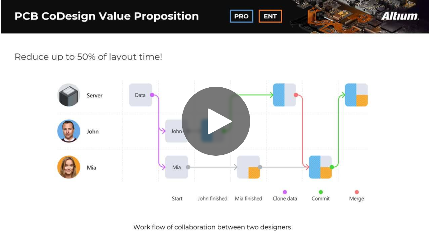
Expand your collaboration skills and stay ahead of the curve with PCB CoDesign. Design teams often grapple with prolonged design cycles and coordination issues, leading to delays and inefficiencies. In the current landscape, design processes are hindered by fragmented collaboration, resulting in increased layout times and difficulties in synchronizing design updates.