Welcome, Guest

Sign in to learn, create, and do more with the product you love.

News & Updates

Filters:
Tag
Embedded thumbnail for Design RF PCB: Plane Connect -direct
RF PCB Design
Design RF PCB: Plane Connect -direct

It is bad practice to use thermal reliefs to connect pads in RF path circuits. We'll show you how to quickly and easily change pad-to-polygon connection style to direct connection.

Embedded thumbnail for Precise Selection with PCB Filter
How to work with Selection
Precise Selection with PCB Filter

Narrowing down a precise and accurate selection of objects can be difficult on a crowded board. Learn about the PCB Filter panel, how to use it to create queries to select objects on the PCB, and how to create design rules from these queries.

What is the PCB Supply Chain?
Blog
What is the PCB Supply Chain?

The PCB supply chain encompasses multiple components, raw materials, and the PCB itself. PCBs and PCB assemblies are often the most technically complex components that are purchased for electronic assemblies and products. The complexity of modern PCBs leads to several challenges for a supply chain management team that may be significantly different when compared with other commodities the team manages. In this brief guide, we'll look in-depth at the PCB supply chain, and specifically what falls within the purview of a procurement and supply chain management team.


Embedded thumbnail for Rigid-Flex Board Shape Design in MCAD
Working with MCAD CoDesigner extension
Rigid-Flex Board Shape Design in MCAD

The MCAD Codesigner allows you to design or edit your board shape in the MCAD environment and have it pushed back to Altium Designer. We’ll show you how to configure the board shape, rigid and flex regions, and mounting holes.

What is mode conversion
Blog
A Guide to Mode Conversion, Its Causes, and Solutions

On interconnects, such as board-to-board connections or cascaded transmission line arrangements, you have an important EMC compliance metric that is sometimes overlooked. This is mode conversion, which can be visualized in an S-parameter measurement for differential and common-mode signal transmission. In this article, we’ll look at a short overview of mode conversion in high-speed design with some examples from common differential standards.

Embedded thumbnail for Design RF PCB: routing (any angle, arc)
RF PCB Design
Design RF PCB: routing (any angle, arc)

It is worth taking a responsible approach to the shape and size of the RF signal conductors. In this video we will cover some practical aspects of working with routing such nets in Altium Designer.

Embedded thumbnail for Component Placement in Rigid-flex PCB
Working with MCAD CoDesigner extension
Component Placement in Rigid-flex PCB

With the MCAD CoDesigner you can quickly add and move components from your MCAD tool and update the design automatically in Altium Designer. We’ll show you how to add a new component, move components, change a component’s region in MCAD, and update your design in Altium Designer.

Pad and via sizing
Blog
PCB Via Size and Pad Size Guidelines

There are some aspects of PCB design and layout that seem deceptively simple, and yet they have a complex answer that is related to many important aspects of manufacturing. One of these design aspects is the match between PCB via size and pad size. Obviously, these two points are related; all vias have a landing pad that supports the via and provides a place to route traces into a via pad. However, there are some important sizing guidelines to follow when the matching pad and via sizes, and this match is an important element of DFM and reliability.
Differential Microstrip Impedance
Blog
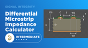
Differential Microstrip Impedance Calculator

Are you looking for a free tool that you can use to calculate the impedance of differential microstrips? We created a simple tool you can use to calculate differential microstrip impedance for a given geometry and dielectric constant. If you’ve been looking for an accurate differential microstrip impedance calculator, then the calculator below is certainly one of the best free tools you’ll find on the internet before you start using field solvers to determine differential pair impedance.

Embedded thumbnail for Transmission lines (coplanar)
RF PCB Design
Transmission lines (coplanar)

The boards use transmission lines to carry high-frequency signals. In addition to microstrip lines, coplanar transmission lines with a ground reference polygon are often found on boards. Coplanar transmission lines propagate the same wave type as microstrip transmission lines, but the electromagnetic field is more concentrated near the conductor, so coplanar lines have lower losses at high frequencies, less dispersion, and less interference to adjacent circuits.

Embedded thumbnail for How to Reuse Board Shapes in MCAD
Working with MCAD CoDesigner extension
How to Reuse Board Shapes in MCAD

You can use the MCAD Co-designer panel to reuse your board shape or geometry in your PCB. We’ll show you how to use the MCAD Co-designer panel in Altium Designer and how to copy your board shape and geometry from your MCAD tool to Altium Designer.

PCB DFM Check
Blog
Getting Through a PCB DFM Check

In this article, we’ll discuss the key design features to implement, and steps to take prior to fabrication that will help prevent some common DFM problems. I’ll also provide examples of where I commonly see these PCB DFM problems in signal integrity circuits.


Embedded thumbnail for Selection filter - Panel Properties and PCB
How to work with Selection
Selection filter - Panel Properties and PCB

Learn how to configure the types of selected objects using the Selection Filter. In addition, you will learn about the Post Selection Filter and its features.

Spreading Inductance
Blog
What is Spreading Inductance?

If you’re working with a high-speed digital component, there are some simple power integrity rules that should be followed. However, there is one quantity that is sometimes ignored when building a PDN impedance simulation: the spreading inductance of your plane pair. Here are some points designers should know about the spreading inductance of a plane pair.

Embedded thumbnail for PCB Origins During the ECAD MCAD Exchange
Working with MCAD CoDesigner extension
PCB Origins During the ECAD MCAD Exchange

Origins can vary from your MCAD tool and Altium Designer. With the MCAD Co-Designer panel Altium Designer can keep track of your origin point and make sure your design changes are exchanged correctly.

Embedded thumbnail for Global Editing Using Find Similar Objects
How to work with Selection
Global Editing Using Find Similar Objects

Editing multiple objects one by one can be a very time consuming process. Altium Designer makes this easy and efficient with the Find Similar Objects tool, which allows you to globally select and edit multiple objects at once.

PCB Design Basics for New Designers
Blog
PCB Design Basics for New Designers

In this article, I’ll present some design basics that every new designer should follow to help ensure their design process is successful. Some of these points may challenge the conventional view of how circuit boards are constructed, but they are intended to help balance low noise signaling, manufacturability, and ease of solving a layout.
Selecting Materials for High Voltage PCB Design and Layout
Blog
Selecting Materials for High Voltage PCB Design and Layout

High voltage PCBs are subject to certain safety and reliability concerns that you won’t find in most other boards. If your fabrication house specializes in high voltage PCBs and keeps materials in stock, they can likely recommend a material set, as well as a standard stackup you might use for certain voltage ranges and frequencies. If you need to choose your own materials, follow the tips below to help you narrow down to the right material set.

Embedded thumbnail for Shaping the PCB in MCAD
Working with MCAD CoDesigner extension
Shaping the PCB in MCAD

Through the MCAD Co-designer in Altium Designer, you can collaborate with a mechanical engineer to shape the PCB in your MCAD tool and keep it updated in Altium Designer. We’ll show you how in Altium Designer and in your MCAD tool.

Embedded thumbnail for Cross Select Mode
How to work with Selection
Cross Select Mode

Cross Select Mode is a unique tool that allows for cross-selection of objects between the schematic and PCB thanks to the Altium Unified platform. This makes it easy to look for specific components, as well as take advantage of component placement tools.

Tag
Molded Interconnect Devices
Blog
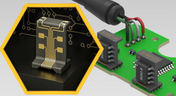
MIDs Make a Comeback as Vertical SMD Modules for Your PCB

Molded interconnect devices are essentially plastic molded substrates with traces running along any surface, including at right angles and running vertically. Altium users can use the new 3D Routing extension to design their own component carriers, which can be mounted vertically in a standard assembly process. If you’ve always wanted to vertically mount components or entire circuits, but without the expense of adding a flex section to your design, the new 3D Routing extension with HARTING’s component carrier designs provides a unique solution.
MCAD CoDesign Process
Blog
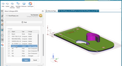
MCAD CoDesigner 2.9.0 is Out

Altium has released version 2.9.0 of the MCAD CoDesigner. This version has the option to exclude small components when transferring from ECAD to MCAD. The arc behavior was improved, and the support for splines in board shape and cutouts was added. With this release, you can now select a specific SOLIDWORKS configuration of a part to use on the board and view the improvements made for Siemens NX.

Rigid-Flex in Altium Designer
Blog
Support for Rigid-Flex in Altium Designer

Altium Designer's world-class PCB design features help users quickly get started with new rigid-flex designs and prepare them for manufacturing. Rigid-flex in Altium Designer starts with designing a manufacturable PCB layer stack complete with via transitions and any calculated impedance requirements. Keep reading to see how Altium Designer supports your flex and rigid-flex designs.
2+N+2 PCB Stackups
Blog
2+N+2 PCB Stackup Design for HDI Boards

Like any other advanced PCB, success in HDI design comes from designing the right stackup. One common HDI stackup used to support routing into moderate pin count, high-density BGA components is the 2+N+2 PCB layer stack for HDI boards. We’ll explore this stackup more in this article, as well as how it is related to other advanced stackups used in HDI PCBs.
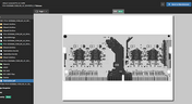
PDF Viewer in Altium 365
Blog
PDF in Altium 365 Web Viewer

Altium 365 Web Viewer now includes a built-in PDF viewer that allows you to view PDF files in releases without an external PDF viewer application. Keep reading to learn about new key features that make your work easier

Rigid-Flex Applications
Blog
Flex and Rigid-Flex PCB Applications

There are two basic reasons for designing a flex circuit into your product: to build a compact and efficiently assembled device, or to make the circuit dynamically integrated with the mechanical function of the product. You may, of course, lean on both of these reasons for justifying the use of flex circuits. On this note, let’s look at some rigid-flex PCB applications and design examples to see the issues that spring to mind when designing flex circuits
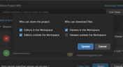
Sharing Settings in Altium 365
Blog
Granular Sharing — Role and Group Management

With Altium 365, you can grant permission to teams or users based on the specific needs of a project. We have expanded Altium 365’s file-sharing setting, giving you more granular control over who can download source files and reshare projects with others

Use your DRCs
Blog
Design Rule Checking in the PCB Design Workflow

Any time you design a PCB, and you want to turn it into a real product, you will have to make sure the design obeys the constraints within the standard PCB manufacturing process. This imposes multiple rules on any design, and ECAD software will enforce design rules as you create the board to ensure you obey these important constraints. Make sure you enforce the right design rules at the beginning of the PCB design workflow 
How to select high frequency materials
Blog
Best Practices for High-Frequency PCB Material Selection

High frequency PCB design can seem esoteric, and I've heard many an engineer describe it as "black magic"! The subject is also a bit confusing, especially once someone asks which frequencies could be reasonably considered "high". Before you do anything inside the layout for a high-speed or RF PCB, you will need to pay attention to the materials being used in the board. If you're unsure which high frequency PCB materials you should use, then keep reading to learn more.

PCB Noise Reduction
Blog
PCB Noise Reduction: Do You Need Isolation, Shielding, or Filters?

Of all the noise and operational challenges designers face in their PCBs, there is one overarching problem that is arguably most popular: electronic noise. It could originate as an SI/PI problem, it could possibly arise from some external source, or it could be good old-fashioned crosstalk! These tend to fall into three categories: adding shielding, doing something to create isolation, or placing filters. Let's look at all of these as they tend to be the default solution set when confronted with many noise problems.
What’s New in Altium 365
Blog
What’s New in Altium 365: Version Control for Hardware, Layer Stackup in Web Viewer, and SOC 2 Type 1 Certification

In February, we hit a new record in the number of users on the platform. The Altium 365 user community is now 20,000 strong! You can now migrate from an external version control system to Altium 365 preserving the history of commits. We also received the SOC 2 Type 1 certification from KPMG, made layer stack available in the web viewer, and added the brand new capability to track tasks in the context of your design project. Keep reading to learn more!

Rigid-Flex in Altium Designer
Blog
Support for Rigid-Flex in Altium Designer

Rigid-flex in Altium Designer starts with designing a manufacturable PCB layer stack complete with via transitions and any calculated impedance requirements. Flex sections also need to be placed in the layer stack before moving into the PCB layout. Once inside the PCB editor, bending lines can be clearly defined in the PCB layout, and these can be visualized in Altium Designer's 3D PCB design tools. Keep reading to see how Altium Designer supports your flex and rigid-flex designs.
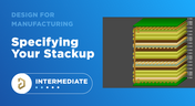
Specifying your stackup
Blog
Communicating PCB Layer Stackup Needs to Manufacturers

In the business of PCB design, communicating needs to manufacturers and vendors is a top priority. The context of our requests is sometimes lost either by not providing the correct information, not listing enough information, or not giving any information. Although the experienced PCB designer can take steps to specify everything they want to see in their PCB stackup, eventaully the manufacturer will handle that decision in an effort to balance available materials with processing capabilities and yield.

Risk Vs. Reward
Blog
Risk Vs. Reward

During the recent IPC APEX expo, there was a lot of discussion about SAP, or semi-additive PCB processes.  As with any new technology adoption there were people that are excited to jump right in and start designing with much finer feature sizes and work through the inevitable changes to the traditional thought process. Others are in a "let’s wait and see" mode and of course there are a few skeptics there as well, so keep reading to learn more.
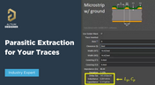
Parasitic Extraction for your traces
Blog
Parasitic Extraction with an Electromagnetic Solver in PCB Routing

Parasitic extraction: the integrated circuit design community must grapple with this task on a daily basis, especially once gate features are reduced below ~350 nm and chips run at high switching speeds. The PCB community also has to deal with this idea in order to better design power delivery networks, interconnects with precise impedance, and properly quantify crosstalk and coupling mechanisms.

Tag
NEW
Embedded thumbnail for EMI Filters & TVS Diodes on High-Speed Interfaces (Done Right)
How-To's
EMI Filters & TVS Diodes on High-Speed Interfaces (Done Right)

Watch the Altium Academy tutorial to learn about a common mistake when designing interfaces exposed through connectors such as USB, HDMI, and similar high-speed interfaces. Discover how to properly select and apply EMI filters, common-mode chokes, and TVS diodes to protect high-speed data lines without compromising signal integrity.

NEW
Embedded thumbnail for Coming Soon: Advanced Via Fencing
New in Altium's Software
Coming Soon: Advanced Via Fencing

Coming soon to Altium software: Advanced Via Fencing gives you greater control over creating and managing shielding and stitching vias for RF and high-speed designs. Configure via fences directly from the Properties panel, follow traces or geometry edges, use stacked vias, define spacing and patterns, and preview the results before generating them.

Embedded thumbnail for 5 DC Power Integrity Myths That Ruin Your PCB Design
How-To's
5 DC Power Integrity Myths That Ruin Your PCB Design

DC power integrity plays a critical role in the reliability of nearly every power electronics board, yet common misconceptions can lead to costly design decisions. In this video, we break down five of the most common DC power integrity myths and explain what you really need to know for reliable power electronics design.

Embedded thumbnail for A fraction of a millimeter is the difference between a robot that fits and one that doesn't
Collaborative Engineering with Team Ribbot
A fraction of a millimeter is the difference between a robot that fits and one that doesn't

Check out the latest episode about Team Ribbot and see how they move design data between their electrical and mechanical tools without losing accuracy. Discover how Altium Designer and MCAD CoDesign help bring the boards, housings, and custom motors together right the first time with no surprises.

Embedded thumbnail for  HDI PCB Stackup Breakdown - Etching Weight Via Spacing, & More
How-To's
HDI PCB Stackup Breakdown - Etching Weight Via Spacing, & More

HDI PCB design depends on getting the stackup and manufacturing constraints right. In this deep dive, we examine a real HDI audio-interface board and explore common pitfalls, from how copper weight and etching affect minimum clearances to why solder mask slivers below 1 mil can cause manufacturing issues. You’ll also learn how proper board-edge clearance and copper pullback help protect SMD pads during routing.

Embedded thumbnail for  How do you review a robot design when your team is never in the same room?
Collaborative Engineering with Team Ribbot
How do you review a robot design when your team is never in the same room?

Team Ribbot’s engineers are spread across five states and juggle full-time jobs while building a 250-pound combat robot in their spare time. Discover how Altium Designer and Altium 365 keep the team connected, letting engineers open the live design from a laptop or phone, inspect the board in 3D, and leave comments directly on the design.

Embedded thumbnail for  Improve Visual Accuracy with True Arcs
New in Altium's Software
Improve Visual Accuracy with True Arcs

Discover how True Arc Rendering improves arc visualization in the PCB Editor and PCB Library Editor by displaying true arcs across 2D, 3D, and Board Planning modes. This provides a more accurate representation of board geometry and helps you work with curved features with greater precision throughout the design process.

Embedded thumbnail for Two engineers, one board, nobody's work gets wiped out
Collaborative Engineering with Team Ribbot
Two engineers, one board, nobody's work gets wiped out

When Team Ribbot’s electrical and mechanical engineers work on the same combat-robot design, unwanted changes can mean hours of lost work. See how Altium Designer and MCAD CoDesign let the team review and selectively accept changes, enabling seamless parallel collaboration across different locations and schedules.

Embedded thumbnail for Visualize and Refine Your Harness Designs
New in Altium's Software
Visualize and Refine Your Harness Designs

Create detailed views of bundle contents, control wire and cable paths, and rotate physical models to accurately represent the final harness assembly. These capabilities give you greater control over harness design and help ensure your digital model reflects the physical result.

Embedded thumbnail for Introducing Agentic Requirements Engineering
New in Altium's Software
Introducing Agentic Requirements Engineering

Discover a new way to work with Requirements Portal through Agentic Requirements Engineering. AI agents analyze your project data and surface proposals for your approval, reducing friction in requirements management and helping align your team's shared model with your design intent.

Embedded thumbnail for Simplify Rule Set Updates and Replacement
New in Altium's Software
Simplify Rule Set Updates and Replacement

Learn how to import rule sets with greater flexibility in Altium. When importing rules, you can add new rules to your existing set, replace only rules that match, or completely replace the current rule set giving you full control over how design rules are updated.

Embedded thumbnail for  How Team Ribbot fits 40 kW of power into a 250-pound combat robot
Collaborative Engineering with Team Ribbot
How Team Ribbot fits 40 kW of power into a 250-pound combat robot

What do you get when you pack the power of a small electric car into a combat robot with virtually no room to spare? In the first episode of our collaboration with Team Ribbot and Altium, explore how seamless ECAD-MCAD collaboration helps the team tackle complex design challenges, optimize high-performance designs, reduce errors, and bring products to life faster.

Embedded thumbnail for Just Released: Supplier Data Merging
New in Altium's Software
Just Released: Supplier Data Merging

Discover how the Supplier Data Merging feature brings together supplier information from your custom parts database and the Altium Parts Provider into a single, unified view. Access consolidated supplier data wherever supplier part numbers appear, including in ActiveBOM and during component selection.

Embedded thumbnail for How Altium’s Layer Stack Manager Actually Works
How-To's
How Altium’s Layer Stack Manager Actually Works

Take a look inside Altium's Layer Stack Manager and discover how its impedance calculator determines the ideal trace width for your target impedance. In this video, we break down the "black box" behind the calculation and show how the Simbeor-based field solver provides accurate results while eliminating the need for advanced field solver expertise.

Embedded thumbnail for Connect Requirements Directly to Your PCB Design
New in Altium's Software
Connect Requirements Directly to Your PCB Design

See how the Requirements Portal integration in Altium Designer simplifies requirements management by bringing system requirements directly into your PCB design workflow. Connect requirements to design documents, assign tasks, track verification in real time, and keep your entire team aligned with seamless synchronization in Altium 365.

Embedded thumbnail for SFP Connector Routing: High-Speed Differential Pair Design Tips
How-To's
SFP Connector Routing: High-Speed Differential Pair Design Tips

Discover practical SFP and SFP+ routing tips in our latest video, inspired by a real question from the Altium subreddit. We cover how aggressive serpentine length tuning can be, how to reduce impedance discontinuities in tight meanders, and how meandering influences mode conversion at 10G and higher data rates.

Tag
Your search returns no results.