News & Updates

Blog
•
Altium Designer 22.6 Update
We are happy to announce that the Altium Designer 22.6 update is now available. Altium Designer 22.6 continues to focus on improving the user experience, as well as performance and stability of the software, based on feedback from our users. Check out the key new features in the What's New section on the left side of this window!

Blog
•
Join PCB Design Review Competition from Altium
Find 9 mistakes in a PCB design and get added into the lucky draw to win a prize from Altium!

Blog
•
SAP (Semi-Additive PCB Process) – Top 5 Questions Regarding Stack Up
This Semi-Additive Process is an additional tool in the PCB fabricators' toolbox that enables them to provide feature sizes for trace width and spacing that are 25 microns, (1 mil) and below depending on the fabricators' imaging equipment. This provides much more flexibility to breakout out tight BGA areas and the ability to shrink overall circuit size and/ or reduce the number of circuit layers in the design. As the PCB design community embraces the benefits of this new printed circuit board fabrication technique, there are of course many questions to be answered.



Blog
•
Improving Supply Chain Success with BOM Management
It’s no secret that component shortages have become more frequent this year. In fact, countries around the world are losing billions in revenue due to supply issues. Having the right components on hand is more crucial than ever as availability, obsolescence, counterfeit products and environmental non-compliance risks continue to grow. Fortunately, many shortages can be avoided by introducing proactive supply chain practices.
Blog
•
What is the Impedance of Length-Tuning Structures?
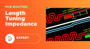
Do length-tuning structures create an impedance discontinuity? The answer is an unequivocal “yes”, but it might not matter in your design depending on several factors. Applying a length-tuning structure is equivalent to changing the distance between the traces while meandering. Therefore, you will have a change in the odd-mode impedance of a single trace. The question then becomes: does this deviation in trace impedance in a length tuning structure matter?



Blog
•
A-SAP™ – What do you need to know?
The continued miniaturization of both packaging and component size in next-generation electronics is becoming harder and harder to work around and presents a significant challenge for both PCB designers and PCB fabricators. To effectively navigate the constraints of the traditional subtractive-etch PCB fabrication processes, PCB designs require advanced PCB fabrication capabilities while pushing the limits of finer feature size, higher layer counts, multiple levels of stacked micro vias and increased lamination cycles.


Blog
•
Pin-Package Delay and Via Delay in High Speed Length Tuning
Take a look at the inside of some integrated circuit packages, and you’ll find a number of wires bonded to the semiconductor die and the pads at the edge of the component's package. As a signal traverses makes its way along an interconnect and into a destination circuit, signals need to travel across these bond wires and pads before they are interpreted as a logic state. As you look around the edge of an IC, these bond wires can have different lengths, and they incur different levels of delay and contribute to total jitter.



Blog
•
6-Layer PCB Design Guidelines
Once you’ve run out of room on your 4-layer PCB, it’s time to graduate to a 6-layer board. The additional layer can give you room for more signals, an additional plane pair, or a mix of conductors. How you use these extra layers is less important than how you arrange them in the PCB stackup, as well as how you route on a 6-layer PCB. If you’ve never used a 6-layer board before, or you’ve had EMI troubles with this stackup that are difficult to solve, keep reading to see some 6-layer PCB design guidelines and best practices.
Blog
•
Altium Designer 22.5 Update
We are happy to announce that the Altium Designer 22.5 update is now available. Altium Designer 22.5 continues to focus on improving the user experience, as well as performance and stability of the software, based on feedback from our users. Check out the key new features in the What's New section on the left side of this window!

Blog
•
How Reliable is Your Hybrid PCB Stackup?
PCB stackups often incorporate slightly dissimilar materials that could pose a reliability problem. Hybrid PCBs are one case where the PCB stackup will include different materials, typically a standard FR4 laminate and a PTFE laminate for RF PCBs. Designers who want to take the lead on material selection when designing their hybrid stackups should consider these factors that affect reliability. As with any PCB stackup, make sure you get your fabricator involved in the manufacturing process early to ensure reliability problems do not arise during production.
Blog
•
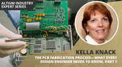
The PCB Fabrication Process—What Every Design Engineer Needs To Know, Part 1
There are still a number of designers - perhaps most of them - who have never toured a PCB fabrication facility. They are also unaware of the various steps that occur during the fabrication process. The purpose of this article is to describe those steps and what transpires in each of them. Part 1 of this article focuses on inner layer processing and the steps that are done prior the lamination process.
Blog
•
Webinar "8 Reasons to Store Your Components in Altium 365"
Working with local libraries seems like a simple solution, but we often don’t take into account the added time spent maintaining libraries and sharing them between team members. This webinar showcases the advantages of component storage in Аltium 365 to resolve the issues of local libraries and component management.

Blog
•
Bridging the Gap Between Designers and Customers
Every piece of electronic equipment starts with a great idea. Transforming great ideas into real, physical products takes a team of talented individuals and multiple companies coming together to make everything from the internal components to the external hardware. Paul Payen de la Garanderie, Founder and Owner of AW Audio, an engineering services company based in France, understands these challenges very well. With an extensive background in the Audio/Visual industry, Paul has had to work with multiple companies over the years, from small start-ups to celebrated AV firms.

Blog
•
Additive PCB Manufacturing: The Vaccine for Electronics Supply Shocks?
At this time, at least a quarter of the world’s population is under quarantine, with workers unable to go to offices or factories, leading to fundamental disabling of the world economy. The electronics industry is suffering greatly as well, dealing with a supply shock from factories shutting down in Southeast Asia, to demand-side shocks from Western markets literally shutting down. Now it is the electrical engineers taking the lead with additive PCB manufacturing.

Blog
•
Webinar "6 Steps to Master Project Storage"
Altium 365 provides a secure cloud platform to store all of your design files in a single place so you can share them with anyone and access them from anywhere. This webinar discusses the advantages of placing, storing, and working with projects in Altium 365.

Blog
•
Altium Designer 20 Changed My Layout Design Routines
I just finalized my first PCB design using Altium Designer 20. At the same time, I tested some new AD20 features, and in this article, I’ll share my thoughts about new layout design features which made the biggest impression for me: sliding, and any-angle routing.

Blog
•
Designing for Antenna Isolation in Your Wireless System
Anyone who has taken apart an old cell phone or designs IoT devices knows multiple communication capabilities are present in these designs, each requiring different antennas. The RF designer should already take precautions for interconnect isolation, but antenna isolation is just as important when modeling and designing wireless systems.

Blog
•
PCB Trace and Pad Clearance: Low vs. High Voltage
High voltage/high current designs carry safety requirements which need to be met by designers. Similarly, high speed designs need to have suppressed crosstalk in order to ensure signal integrity. The key design aspects that relate to both areas are your PCB trace clearance and pad clearance values. These design choices are critical for balancing safety, noise suppression, and manufacturability.
Blog
•
Getting Through PCB DFM
In this article, we’ll discuss the key design features to implement, and steps to take prior to fabrication that will help prevent some DFM process pain.

Blog
•
Level Up Your Design Skills - Altium Designer Getting Started User Guide Update
We are happy to announce the new update of our Altium Designer Getting Started User Guide. Whether you are new to Altium Designer or you want to brush up on some topics, the Altium Designer Getting Started User Guide will take you from a beginner to a master in PCB design.
This is only the beginning! This guide will be updated with new information based on user feedback. Let’s first go over the contents of the guide.

Blog
•
Modeling Copper Foil Roughness in Altium Designer's Impedance Profiler
With the new layer stack manager in Altium Designer®, you can now include copper foil roughness factors directly in your impedance calculator. This is quite easy to do in the layer stack manager, but it begs the question: what exactly is the copper roughness factor? Which value should be used for your interconnects?

Blog
•
High-Speed Signal Routing: The 5 Important Constraints
After you capture your schematic as an initial layout and create an initial component arrangement, it’s time to define your routing constraints. Doing this early will allow your DRC engine to spot rules violations before you finish your layout. Likewise, you’ll be able to modify the default rule set to meet your layout requirements. Here are the important routing constraints you’ll need to check before you start routing your board.
Blog
•
CoDesigner and MCAD Component Placement On-Demand Webinar
Learn how to place components from the MCAD side and synchronize them with Altium Designer ECAD models, designators, and sourcing data to simplify your design process.
Blog
•
How to Create a PCB Manufacturing Cost Estimation
Some manufacturers have very convenient PCB manufacturing cost estimation calculators you can use, but the real costs depend on a number of factors. If you’re an entrepreneur and you’re producing your own boards, or you are managing manufacturing, testing, and delivery for a new project, it’s your job to help clients understand the primary cost drivers for new boards. Here’s how you can get an estimate of your fabrication costs, both for local and overseas manufacturers.
Blog
•
PCB Mountable Connectors: SMD vs. Through-hole
Selecting a connector is as much an art as it is a science. The artistic side is all about aesthetics and satisfying clearances, while the scientific side is all about signal integrity. For PCB mountable connectors, you’ll need to choose between surface-mounted or through-hole connectors, and you’ll need to consider how each type affects signal integrity in your application. Here’s what you need to think about beyond the standard connector specifications.

Blog
•
PCB Via Current-Carrying Capacity: How Hot is Too Hot?
Trace and via current-carrying capacity are legitimate design points to focus on when designing a new board that will carry high current. The goal is to keep conductor temperatures below some appropriate limit, which then helps keep components on the board cool.














Your search returns no results.


