News & Updates

Blog
•
Master Your Circuit Design: Dive into Worst Case Analysis
Dive into Worst Case Analysis techniques with Kamil Jasiński and ensure the reliability of your circuits. Master sensitivity analysis, Monte Carlo simulations, and more to confidently address real-world challenges.

Blog
•
Overview of the Gerber X3 File Format
Want to learn how the Gerber X3 file format simplifies data exchange by unifying assembly and fabrication details in a single file? This article explores the format and its role in streamlining PCB manufacturing.

Blog
•
Save Time and Prevent Errors in Cable Harness Design Today
Our new article explores best practices and tools for streamlining cable harness design workflows. Learn how to minimize errors, save time, and enhance collaboration by leveraging advanced features in Altium Designer.
Blog
•
Mastering EMI Control in PCB Design: How to Design PCBs for Low EMI
This article by Dario Fresu delves into effective techniques for designing PCBs to reduce electromagnetic interference (EMI). It covers key topics such as stackup selection, routing strategies, and grounding best practices, offering actionable insights for improved performance.

Blog
•
Altium and Renesas’ Role in Enabling Economy 4.0 is the Subject of New Documentary
Altium and Renesas are featured in a new CBS-produced documentary exploring how digitalization and cloud platforms are revolutionizing electronics production for Economy 4.0, driving efficiency and accelerating innovation.


Blog
•
Avoid Wiring Errors with Tools Tailored for Harness-to-PCB Integration
Discover how to streamline your wiring projects with advanced harness and PCB integration tools in Altium Designer. This article explores techniques to prevent wiring errors, enhance collaboration, and ensure accurate design documentation for complex projects.

Blog
•
Happy Holidays!!!
Altium wishes you all the best this holiday season! May this time be filled with joy, laughter, and cherished moments with your family and friends. We also extend our warmest wishes for a Happy New Year 2025!



Blog
•
What Is Wire Harness Design?
Explore our latest article to learn the fundamentals of wire harness design, its key components, and how it ensures organized, efficient, and reliable electrical systems across automotive, aerospace, and medical sectors.



Blog
•
How to Determine Ferrite Bead Circuit Model Parameters
Learn how to accurately determine ferrite bead circuit model parameters for effective noise suppression in high-speed PCB designs. This article explores key concepts, measurement techniques, and practical tips for modeling ferrite beads in your projects.


Blog
•
PCB Via Current-Carrying Capacity: How Hot is Too Hot?
One common question from designers is current-carrying capacity of conductors in a PCB. Trace and via current-carrying capacity are legitimate design points to focus on when designing a new board that will carry high current. The goal is to keep conductor temperatures below some appropriate limit, which then helps keep components on the board cool. Let’s dig into the current state of thermal demands on vias in PCBs and how they compare to internal and external PCB traces.

Blog
•
Phalanx, not Failure: PCB Shielding to Protect Your Design
A combination of good printed circuit board design and good shielding mitigates EMI. Good PCB design for EMI shielding revolves around the layout, the placement of filters, and ground planes. A well-designed PCB minimizes parasitic capacitance and ground loops. Keep reading to learn more about PCB shielding.
Blog
•
Best Practices in Hardware Version Control Systems
Any project can get very complex, and the PCB design team needs to track revisions throughout a project. Why worry about tracking revisions? In the event you ever receive changes to product functional requirements, major changes are made to your product’s architecture, or you’re ready to finalize the design and prepare for fabrication, it’s best to clone a project at its current state and begin working on a new version. Keeping track of all these design changes in a PCB design project takes the type of hardware version control tools you’ll find in Altium 365™.

Blog
•
Copper Pour and Via Stitching: Do You Need Them in a PCB Layout?
To pour or not to pour, to stitch or not to stitch… Over many years, some common “rules of thumb” have become very popular and, ultimately, taken a bit out of context. Rules of thumb are not always wrong, but taking PCB design recommendations out of context helps justify bad design practices, and it can even affect the producibility of your board. Like many aspects of a physical PCB layout, via stitching and copper pour can be like acid: quite useful if implemented properly, but also dangerous if used indiscriminately.
Blog
•
Should You Use Power MOSFETs in Series?
Power MOSFETs enable a huge range of electronic systems, specifically in situations where BJTs are not useful or efficient. MOSFETs can be used in high current systems in parallel arrangements, but what about their use in series? Both arrangements of MOSFETs have their pitfalls that designers should consider. Let’s look at MOSFETs in series as they are quite useful in certain systems, but be careful to design your circuits and your PCB for reliability.

Blog
•
Controlled ESR Capacitors: Should You Use Them for Power Integrity?
I can’t think of a single product I’ve built that doesn’t require capacitors. We often talk a lot about effective series inductance (ESL) in capacitors and its effects on power integrity. What about effective series resistance (ESR)? Is there a technique you can use to determine the appropriate level of resistance, and can you use ESR to your advantage?
Blog
•
Microstrip Ground Clearance Part 2: How Clearance Affects Losses
If your goal is to hit a target impedance, and you’re worried about how nearby pour might affect impedance, you can get closer than the limits set by the 3W rule. But what are the effects on losses? If the reason for this question isn’t obvious, or if you’re not up-to-date on the finer points of transmission line design, then keep reading to see how nearby ground pour can affect losses in impedance-controlled interconnects.
Blog
•
Choosing the Right Microphone for Embedded Applications
If you need to capture sound waves for your electrical device to process, you'll need a microphone. However, microphones these days have become very advanced, and there are so many options to choose from. They range from the relatively simple and popular condenser type microphones to state-of-the-art sound conversion solutions incorporating internal amplifiers and other electronic processing functionality. In this article, we'll take a look at some of the options available.

Blog
•
Composite Amplifiers and How They Give the Best of Both Worlds
There are many times where you need an amplifier with high gain, low noise, high slew rate, and broad bandwidth simultaneously. However, not all of these design goals are possible with all off-the-shelf components. Here are some points to consider when working with a composite amplifier design and how to evaluate your design with the right set of circuit simulation tools.
Blog
•
Reduce Common-Mode Noise in Your Power Supply with Impedance Balancing
Simple switching regulator circuits that operate in compact spaces, like on a small PCB, can usually be deployed in noisy environments without superimposing significant noise on the output power level. As long as you lay out the board properly, you’ll probably only need a simple filter circuit to remove EMI on the inputs and outputs. As the regulator becomes larger, both physically and electrically, noise problems can become much more apparent, namely radiated EMI and conducted EMI in the PCB layout.

Blog
•
Part 1: Why Your PCB Design Review Process Is Obsolete and What You Can Do About It
A PCB design review is a practice to review the design of a board for possible errors and issues at various stages of product development. It can range from a formal checklist with official sign-offs to a more free-form inspection of schematic drawings and PCB layouts. For this article, we will not delve into what to check during a design review process but rather look at how a review process itself usually unfolds and how to optimize it to get the most out of your time.
Blog
•
Part 2: Why Your PCB Design Review Process Is Obsolete and What You Can Do About It
As we established in Part 1, the PCB design review and collaboration practices have room for improvement in many organizations. To address this, we developed Altium 365. Let's examine how running a PCB project through Altium 365 compares to other methods.

Blog
•
What is PCB Star Grounding and Why Would Anyone Use It?
If you look on the internet, you'll find some interesting grounding recommendations, and sometimes terminology gets thrown around and applied to a PCB without the proper context or understanding of real electrical behavior. DC recommendations get applied to AC, low current gets applied to high current, and vice versa... the list goes on. One of the more interesting grounding techniques you'll see as a recommendation, including on some popular engineering blogs within the industry, is the use of PCB star grounding.
Blog
•
Your Guide to PCB Silkscreen
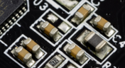
Every PCB has silkscreen on the surface layer, and you’ll see a range of alphanumeric codes, numbers, markings, and logos on PCB silkscreen. What exactly does it all mean, and what specifically should you include in your silkscreen layer? All designs are different, but there are some common pieces of information that will appear in any silkscreen in order to aid assembly, testing, debug, and traceability
Blog
•
What Causes Gibbs Ringing in High-speed Channel Simulations?
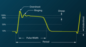
Designing high-speed channels on complex boards requires simulations, measurements on test boards, or both to ensure the design operates as you intend. Gibbs ringing is one of these effects that can occur when calculating a channel’s response using band-limited network parameters. Just as is the case in measurements, Gibbs ringing can occur in channel simulations due to the fact that network parameters are typically band-limited.
Blog
•
Efficient Heat Dissipation with SMD Heat Sinks Keeps You From Dropping PCBs
In electronics, there is the possibility that your PCB can get pretty hot due to power dissipation in certain components. There are many things to consider when dealing with heat in your board, and it starts with determining power dissipation in your design during schematic capture. If you happen to be operating within safe limits in a high power device, you might need an SMD heat sink on certain components. Ultimately, this could save your components, your product, and even the operator.
















Your search returns no results.


