
Welcome, Guest

Sign in to learn, create, and do more with the product you love.

News & Updates

Filters:
Tag
Embedded thumbnail for Unveiling 99% Task Time Efficiency
Altium Designer's 25 Quantitative Benefits
Unveiling 99% Task Time Efficiency

This video showcases Altium Designer 25’s PCB Section View, a powerful tool for detailed circuit analysis and optimization. Learn how it enhances precision, improves performance, and simplifies complex PCB layouts with real-world applications.

Blog
Boost Your PCB Testing Efficiency with Testpoint Manager

Testpoints are essential for efficient PCBA testing and debugging. Our latest whitepaper dives into testpoint optimization, fault detection, and automated testing strategies, along with a full tutorial on using Testpoint Manager in Altium Designer. Discover how to streamline your testpoint assignments and improve measurement accuracy!

Embedded thumbnail for Bottom Terminated Component Guide: Footprint Design Best Practices
How-To's
Bottom Terminated Component Guide: Footprint Design Best Practices

Want to create a reliable footprint for your PCB design? Watch our latest video with Zach Peterson and learn best practices for designing PCB footprints for bottom-terminated components. This tutorial covers how to properly design paste masks for QFNs, BGAs, and other bottom-terminated packages to prevent common assembly issues.

Embedded thumbnail for Design 4x Faster with Altium Designer 25
Altium Designer's 25 Quantitative Benefits
Design 4x Faster with Altium Designer 25

PCB CoDesign in Altium Designer 25 enables multiple engineers to collaborate on a single PCB design, saving over 10 minutes and 300+ clicks. With an intuitive compare-and-merge workflow, teams can efficiently resolve conflicts and streamline their design process. Check out this video to learn more, and use the Benefit Calculator to see your potential time savings: https://www.altium.com/benefit-calculator.

Blog
Ultra HDI: It’s Not Just Buzzword

Ultra-HDI technology is transforming PCB design, enabling unprecedented miniaturization and performance. In this article, explore what sets Ultra-HDI apart from traditional HDI and how it’s shaping the future of electronics.
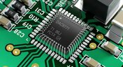

Embedded thumbnail for Empowering Hybrid Designs with Wire Bonding
New in Altium Designer 25
Empowering Hybrid Designs with Wire Bonding

Our latest whitepaper on Wire Bonding technology is now available! It explores the role of wire bonding in modern PCB design and how Altium Designer 25 enhances the process with dedicated features. Access it here: Wire Bonding Whitepaper.

Blog
Cloud PCB Design: 5 Cloud Security Myths Debunked

This article addresses common misconceptions about cloud security in PCB design. It explains how modern cloud platforms, such as Altium 365, often provide superior security compared to traditional on-premises solutions. Key features like advanced infrastructure, granular access controls, and compliance with stringent regulations ensure the protection of valuable design data.
Embedded thumbnail for 8 Times Faster Simulations Using Altium Designer 25
Altium Designer's 25 Quantitative Benefits
8 Times Faster Simulations Using Altium Designer 25

Speed up your simulations with Altium Designer 25—now up to 8x faster! Watch our comparison to see how built-in simulation slashes processing time, saving you valuable minutes on every task.

Embedded thumbnail for Harness Design Top 5 Improvements in Altium Designer 25
New in Altium Designer 25
Harness Design Top 5 Improvements in Altium Designer 25

Harness Design in Altium Designer 25 just got a major upgrade! This video showcases the top five new features that improve flexibility, organization, and efficiency in your wiring workflow. Watch now to see these enhancements in action and take your designs to the next level!

Blog
Renesas and Altium Announce Introduction of Renesas 365, Powered by Altium

Last week, Renesas Electronics and Altium proudly announced the introduction of Renesas 365, Powered by Altium—a first-of-its-kind industry solution designed to streamline electronic system development, from silicon selection to system lifecycle management. Renesas 365 will be demonstrated at Embedded World, Booth 5-371, from March 11-13 in Nuremberg, Germany.

Embedded thumbnail for HitIQ uses Altium solutions to better understand brain injuries in sports sciences
Altium Stories
HitIQ uses Altium solutions to better understand brain injuries in sports sciences

Watch our video about HitIQ and theirs usage of Altium's software to develop a Smart Mouthguard, an advanced concussion management solution. Our software accelerated their development, improved accuracy, and its helpful for detecting and managing sports-related brain injuries.

Blog
DFM/DFA Requirements in Systems Engineering

Learn how integrating DFM and DFA principles into systems engineering ensures manufacturable, cost-effective PCB designs by optimizing CAD, CAM, and requirements management in our new article by Javier Alcina.

Embedded thumbnail for Boost Team Productivity with Seamless Collaboration - Recording Preview
New in Altium Designer 25
Boost Team Productivity with Seamless Collaboration - Recording Preview

Discover how to enhance your PCB design workflow with Altium Designer and Altium 365. Learn to speed up tasks, enhance collaboration, connect teams, and optimize part selection—all in one seamless environment.

Blog
Best Practices for Electronics Project Management - Part 2

Part 2 of this series covers essential project management techniques for electronics design teams. Rafał Stępień discusses effective data organization, revision control, and collaboration strategies to improve efficiency and minimize errors.
Embedded thumbnail for Altium Tutorial: Harness Design to Multi-Board Assembly Workflow
How-To's
Altium Tutorial: Harness Design to Multi-Board Assembly Workflow

Watch our latest tutorial on Harness Design and Multi-board, where we showcase best practices for Harness Design, MCAD collaboration, and manufacturing documentation generation to enhance your PCB assembly workflow.

Blog
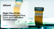
Rigid-Flex PCBs: Understanding the Pros, Cons, and Fabrication Considerations

Read our new article which discusses the advantages of rigid-flex PCBs, such as space-saving designs and enhanced reliability, while also addressing potential challenges in their fabrication. It provides essential design and manufacturing tips to help engineers effectively implement this technology in various applications.


Embedded thumbnail for Smart Mouthguard Impacting Concussion Science
Altium Stories
Smart Mouthguard Impacting Concussion Science

Check out our latest Customer Success Story about HitIQ, founded by former AFL player Nathan Murphy. HitIQ harnessed Altium’s design and collaboration tools to develop its Smart Mouthguard—an advanced concussion management solution. The team utilized Altium Designer’s Rigid-Flex PCB capabilities and Constraint Manager, along with Altium 365’s Web Viewer and Cloud Storage, to create a compact yet highly functional design while enhancing cross-functional collaboration.

Blog
The Role of Automation & Robotics in Wire Harness Assembly

Our new article highlights how automation and robotics are transforming wire harness assembly, improving efficiency, precision, and cost-effectiveness. Technologies like robotic wire handling and AI-driven testing are paving the way for smarter production. However, challenges like custom designs and high costs still persist.
Tag
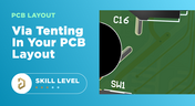
Via tenting in PCB Layout
Blog
When to Use Tented Vias in Your PCB Layout

There are some guidelines I see many designers implement as a standard practice, often without thinking about it. Some of these practices are misunderstood or implemented without best practices. Others are implemented without thinking about the potential problems. One of these is the use of tented vias, which is sometimes implemented in a PCB layout by default. Is this always the right practice?

Capacitive load termination
Blog
How to Impedance Match and Terminate Capacitive Loads

The idea of a purely capacitive load is something of a fallacy. Yes, capacitors exist, but all capacitors are non-ideal, and it is this deviation from a theoretical capacitance that determines how to impedance match a load that exhibits capacitive behavior. Let’s take a look at this important aspect of interconnect design and see what it really means to terminate a capacitive load.
Using Altium 365 Over Your Vanilla Version Control System
Blog
Using Altium 365 Over Your Vanilla Version Control System

There are all sorts of version control systems out there that people have been using with their PCB design software. As discussed in Why Use a Version Control System, we looked at different options ranging for local hard drive storage to sophisticated online revisioning systems. In this article we will be reviewing the differences between a standard VCS and Altium 365.
Why Use a Version Control System in PCB Design
Blog
Why Use a Version Control System in PCB Design

Version Control Systems (VCS) have been around for many decades within the software world but can be surprisingly new to some folks in the electronics design industry. This article will cover what a VCS is, what it does, and why you should be using one for your PCB design projects.

IPC 6012 Class 3 Annular Ring
Blog
Meeting Standards: IPC 6012 Class 3 Annular Ring

Designers often conflate leftover annular ring and pad sizes - they need to place a sufficiently large pad size on the surface layer to ensure that the annular ring that is leftover during fabrication will be large enough. As long as the annular ring is sufficiently large, the drill hit will not be considered defective and the board will have passed inspection. In this article, I'll discuss the limits on IPC-6012 Class 3 annular rings as these are a standard fabrication requirement for high-reliability rigid PCBs.
PCB fabrication notes
Blog
Decoding PCB Fabrication Notes

Sending a board out for fabrication is an exciting and nerve-wracking moment. Why not just give your fabricator your design files and let them figure it out? There are a few reasons for this, but it means the responsibility comes back to you as the designer to produce manufacturing files and documentation for your PCB. It’s actually quite simple if you have the right design tools. We’ll look at how you can do this inside your PCB layout and how this will help you quickly generate data for your manufacturer.

HDI PCB design and HDI PCB manufacturing process
Blog
Design Basics for HDI and the HDI PCB Manufacturing Process

As the world of technology has evolved, so has the need to pack more capabilities into smaller packages. PCBs designed using high-density interconnect techniques tend to be smaller as more components are packed in a smaller space. An HDI PCB uses blind, buried, and micro vias, vias in pads, and very thin traces to pack more components into a smaller area. We’ll show you the design basics for HDI and how Altium Designer® can help you create a powerful HDI PCB.
All About PCB Test Points
Blog
Is It Printed or a Component? All About PCB Test Points

Test points in your electronic assembly will give you a location to access components and take important measurements to verify functionality. If you’ve never used a test point or you’re not sure if you need test points, keep reading to see what options you have for test point usage in your PCB layout.

How to Design to a Differential Impedance Specification
Blog
How to Design to a Differential Impedance Specification

The concept and implementation of differential impedance are both sometimes misunderstood. In addition, the design of a channel to reach a specific differential impedance is often done in a haphazard way. The very concept of differential impedance is something of a mathematical construct that doesn’t fully capture the behavior of each signal in a differential trace. Keep reading to see a bit more depth on how to design to a differential impedance spec and exactly what it means for your design.
Product Lifecycle Management in Electronics Manufacturing
Blog
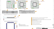
Product Lifecycle Management in Electronics Manufacturing

An effective product lifecycle management (PLM) solution will integrate the tools and processes employed to design, develop and manufacture a new device. This solution goes beyond engineering activities to include the project management, process control, and financial management of the end-to-end business processes. PLM solutions create this collaborative environment where product development can flourish, bringing additional benefits in efficiencies and transparent communications, breaking silos, and speeding up the development process.
Tight versus loose coupling
Blog
Should You Use Tight vs. Loose Differential Pair Spacing and Coupling?

In this article, we want to get closer to a realistic description of tight coupling vs. loose coupling in terms of differential pair spacing, as well as how the differential pair spacing affects things like impedance, differential-mode noise, reception of common-mode noise, and termination. As we’ll see, the focus on tight coupling has its merits, but it’s often cited as necessary for the wrong reasons.

Engineering Design Review Guide
Blog
How to Solve Your Engineering Design Review Challenges

You’ve possibly gone through plenty of engineering design reviews, both on the front-end of a project and the back-end before manufacturing. Engineering design reviews are performed to accomplish multiple objectives, and with many engineering teams taking a systems-based approach to design and production, electronics design teams will need to review much more than just a PCB layout and BOM. Today’s challenges with sourcing, manufacturability, reliability, and mechanical constraints are all areas that must be confronted in real designs
Schematic Review Checklist
Blog
Schematic Review Checklist

One of the most common points of failure of a device occurs even before you start to layout your circuit board. Mistakes in your schematic design can easily make their way all the way into prototypes or production without a second thought once layout starts. In this article, I’m not going to extol the virtues of a good schematic design. Instead, this article is a simple no frills checklist.

Via current carrying capacity for PCBs
Blog
PCB Via Current-Carrying Capacity: How Hot is Too Hot?

One common question from designers is current-carrying capacity of conductors in a PCB. Trace and via current-carrying capacity are legitimate design points to focus on when designing a new board that will carry high current. The goal is to keep conductor temperatures below some appropriate limit, which then helps keep components on the board cool. Let’s dig into the current state of thermal demands on vias in PCBs and how they compare to internal and external PCB traces.

PCB Shield
Blog
Phalanx, not Failure: PCB Shielding to Protect Your Design

A combination of good printed circuit board design and good shielding mitigates EMI. Good PCB design for EMI shielding revolves around the layout, the placement of filters, and ground planes. A well-designed PCB minimizes parasitic capacitance and ground loops. Keep reading to learn more about PCB shielding.


Tag
NEW
Embedded thumbnail for A fraction of a millimeter is the difference between a robot that fits and one that doesn't
Collaborative Engineering with Team Ribbot
A fraction of a millimeter is the difference between a robot that fits and one that doesn't

Check out the latest episode about Team Ribbot and see how they move design data between their electrical and mechanical tools without losing accuracy. Discover how Altium Designer and MCAD CoDesign help bring the boards, housings, and custom motors together right the first time with no surprises.

NEW
Embedded thumbnail for  HDI PCB Stackup Breakdown - Etching Weight Via Spacing, & More
How-To's
HDI PCB Stackup Breakdown - Etching Weight Via Spacing, & More

HDI PCB design depends on getting the stackup and manufacturing constraints right. In this deep dive, we examine a real HDI audio-interface board and explore common pitfalls, from how copper weight and etching affect minimum clearances to why solder mask slivers below 1 mil can cause manufacturing issues. You’ll also learn how proper board-edge clearance and copper pullback help protect SMD pads during routing.

Embedded thumbnail for  How do you review a robot design when your team is never in the same room?
Collaborative Engineering with Team Ribbot
How do you review a robot design when your team is never in the same room?

Team Ribbot’s engineers are spread across five states and juggle full-time jobs while building a 250-pound combat robot in their spare time. Discover how Altium Designer and Altium 365 keep the team connected, letting engineers open the live design from a laptop or phone, inspect the board in 3D, and leave comments directly on the design.

Embedded thumbnail for  Improve Visual Accuracy with True Arcs
New in Altium's Software
Improve Visual Accuracy with True Arcs

Discover how True Arc Rendering improves arc visualization in the PCB Editor and PCB Library Editor by displaying true arcs across 2D, 3D, and Board Planning modes. This provides a more accurate representation of board geometry and helps you work with curved features with greater precision throughout the design process.

Embedded thumbnail for Two engineers, one board, nobody's work gets wiped out
Collaborative Engineering with Team Ribbot
Two engineers, one board, nobody's work gets wiped out

When Team Ribbot’s electrical and mechanical engineers work on the same combat-robot design, unwanted changes can mean hours of lost work. See how Altium Designer and MCAD CoDesign let the team review and selectively accept changes, enabling seamless parallel collaboration across different locations and schedules.

Embedded thumbnail for Visualize and Refine Your Harness Designs
New in Altium's Software
Visualize and Refine Your Harness Designs

Create detailed views of bundle contents, control wire and cable paths, and rotate physical models to accurately represent the final harness assembly. These capabilities give you greater control over harness design and help ensure your digital model reflects the physical result.

Embedded thumbnail for Introducing Agentic Requirements Engineering
New in Altium's Software
Introducing Agentic Requirements Engineering

Discover a new way to work with Requirements Portal through Agentic Requirements Engineering. AI agents analyze your project data and surface proposals for your approval, reducing friction in requirements management and helping align your team's shared model with your design intent.

Embedded thumbnail for Simplify Rule Set Updates and Replacement
New in Altium's Software
Simplify Rule Set Updates and Replacement

Learn how to import rule sets with greater flexibility in Altium. When importing rules, you can add new rules to your existing set, replace only rules that match, or completely replace the current rule set giving you full control over how design rules are updated.

Embedded thumbnail for  How Team Ribbot fits 40 kW of power into a 250-pound combat robot
Collaborative Engineering with Team Ribbot
How Team Ribbot fits 40 kW of power into a 250-pound combat robot

What do you get when you pack the power of a small electric car into a combat robot with virtually no room to spare? In the first episode of our collaboration with Team Ribbot and Altium, explore how seamless ECAD-MCAD collaboration helps the team tackle complex design challenges, optimize high-performance designs, reduce errors, and bring products to life faster.

Embedded thumbnail for Just Released: Supplier Data Merging
New in Altium's Software
Just Released: Supplier Data Merging

Discover how the Supplier Data Merging feature brings together supplier information from your custom parts database and the Altium Parts Provider into a single, unified view. Access consolidated supplier data wherever supplier part numbers appear, including in ActiveBOM and during component selection.

Embedded thumbnail for How Altium’s Layer Stack Manager Actually Works
How-To's
How Altium’s Layer Stack Manager Actually Works

Take a look inside Altium's Layer Stack Manager and discover how its impedance calculator determines the ideal trace width for your target impedance. In this video, we break down the "black box" behind the calculation and show how the Simbeor-based field solver provides accurate results while eliminating the need for advanced field solver expertise.

Embedded thumbnail for Connect Requirements Directly to Your PCB Design
New in Altium's Software
Connect Requirements Directly to Your PCB Design

See how the Requirements Portal integration in Altium Designer simplifies requirements management by bringing system requirements directly into your PCB design workflow. Connect requirements to design documents, assign tasks, track verification in real time, and keep your entire team aligned with seamless synchronization in Altium 365.

Embedded thumbnail for SFP Connector Routing: High-Speed Differential Pair Design Tips
How-To's
SFP Connector Routing: High-Speed Differential Pair Design Tips

Discover practical SFP and SFP+ routing tips in our latest video, inspired by a real question from the Altium subreddit. We cover how aggressive serpentine length tuning can be, how to reduce impedance discontinuities in tight meanders, and how meandering influences mode conversion at 10G and higher data rates.

Embedded thumbnail for Handle High-Density PCB Layouts with Ease
New in Altium's Software
Handle High-Density PCB Layouts with Ease

Push the limits of PCB design with support for up to 128 signal layers, empowering the development of even the most complex, high-density boards.

Embedded thumbnail for Skip Layer Routing for RF: Control Impedance & Cut Insertion Loss
How-To's
Skip Layer Routing for RF: Control Impedance & Cut Insertion Loss

Discover our latest video and learn how RF designers use a deeper ground plane to minimize skin-effect resistance, improve signal integrity over long high-frequency routes, and optimize impedance matching for oversized SMT pads in antenna launches and coaxial connectors.

Embedded thumbnail for Just Released: ODB++ Intellectual Property Protection
New in Altium's Software
Just Released: ODB++ Intellectual Property Protection

ODB++ Intellectual Property Protection lets you control exactly what design data is included in the ODB++ output, ensuring each manufacturing partner receives only the information needed for their specific fabrication or assembly tasks.

Tag
Your search returns no results.