News & Updates

Blog
•
How to Effectively Use Jira for Hardware Development Projects
Originally built for software development, Jira has become a popular tool for agile project management across various industries. Our new article explores how hardware teams can leverage core Jira features and adapt agile principles to suit the unique needs of hardware development.


Blog
•
Building Supply Chain Resilience: Transforming BOM Management for Modern Electronics
Discover why top electronics companies are replacing spreadsheets with purpose-built BOM management solutions. This whitepaper outlines the risks of outdated methods, offers a readiness checklist, and explores how BOM Portal helps teams cut costs, reduce risk, and speed up development with smarter, data-driven workflows.

Blog
•
Material and Process Considerations That Influence Performance
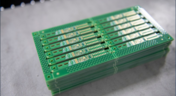
Material and process choices play a key role in high-performance PCB design. This article highlights how stack-up configuration, substrate selection, and lamination strategy impact signal integrity, reliability, and manufacturability.


Blog
•
How to Make Your PCB Layout AOI and X-Ray Friendly
Designing for inspection is key to reliable manufacturing. This article covers practical PCB layout tips to optimize your board for AOI and X-ray inspection helping you reduce defects, false positives, and production delays.


Blog
•
Understanding Systems Engineering
Read our brand-new article where we explore the key areas of an engineering project and the different stages of electronic product development from a project execution perspective. From initiation and planning to design, development, validation, testing, and certification, we walk you through each phase to help you understand how successful electronic products are brought to life.


Blog
•
PCB First-Pass Yield: Small Decisions That Make a Big Difference
This article highlights how seemingly minor layout choices like trace spacing, component footprints, or stack-up details can dramatically impact whether a board passes fabrication and assembly the first time.

Blog
•
Implementing Design for Supply Chain Principles in Electronic Product Development
Designing with supply chain principles in mind helps you avoid delays, reduce costs, and ensure manufacturability. This article outlines practical strategies for component selection, sourcing, and lifecycle management to make your designs more resilient and production-ready.


Blog
•
Beyond the BOM: How Proactive Component Selection Is Transforming Workflows
Learn how proactive component selection helps you avoid supply chain risks, reduce costs, and design more reliably. Our new article outlines key strategies and shows how tools like Altium 365 support smarter part decisions.
Blog
•
Power Integrity Issues?
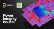
Power problems can be hard to spot until it’s too late. See how easy it is to analyze your power nets, check voltage drops, and improve reliability with Power Analyzer by Keysight - all without leaving your design environment.

Blog
•
How to Design High-Speed PCBs Without Signal Surprises
Signal issues can sneak in early and cost you later. Read our whitepaper to see how Signal Analyzer by Keysight (inside Altium Designer) helps you catch problems fast and design with confidence.


Blog
•
Beyond Basic Part Selection: Using Supply Chain Data to Validate Choices
Learn how to enhance part selection by using real-time supply chain data. This article shows how integrating insights like availability and lifecycle status helps you make smarter, risk-aware design choices.

Blog
•
Signal Mistakes Are Expensive
See how the Signal Analyzer by Keysight in Altium Designer lets you run signal integrity checks directly within your design environment. Read our article to learn how to effectively manage impedance, return paths, stackups, and more.

Blog
•
What You Can Track in Your Altium Project History
When you’re working through a new PCB design project, and you need to keep track of your project revisions, Altium 365™ creates the ideal environment for collaborative PCB design and revision tracking. Once you upload your projects onto the cloud through the Altium 365 platform, Altium 365 creates a Git repository for your project. It allows you to make it available to collaborators through Altium Designer®. This includes a complete project history, which can be easily accessed by collaborators working on a complex project.

Blog
•
Gerber Compare in Altium 365's Online Platform
The moment you push your Gerbers to a manufacturer for a DFM inspection, it can be a nerve-wracking experience waiting for a response. Before you receive your working boards, there will likely be some back-and-forth communication before your board hits the fabrication line. When manufacturers and designers need to resolve problems in Gerber files before fabrication, it helps to have a Gerber compare utility. The newest version of Altium Designer now offers this feature through the Altium 365 platform, giving everyone visibility into changes to Gerbers before fabrication.

Blog
•
California Bets on Electric Cars and Plans to Ban Gasoline Car Sales by 2035
No matter how you might feel about renewable energy and associated environmental issues, electric vehicles are becoming more mainstream and will become the primary mode of transportation in the future. For the engineering community, what’s much more interesting is how our power distribution and management infrastructure can support this shift to massive increases in the use of electricity on the grid. So what’s the rub for PCB designers?
Blog
•
My Favorite Altium Designer Keyboard Shortcuts and Viewing Features
When you’re working through a complex PCB layout, it always helps to know the shortcuts you can use to stay productive. Altium Designer® keyboard shortcuts, and keyboard + mouse shortcuts, can help you easily walk through your PCB layout during design and as part of final checks during a design review. Here are some of my favorite keyboard shortcuts and viewing options that help me stay productive, and I hope they can do the same for you.

Blog
•
The IEEE P370 Standard for High Speed PCB Interconnects
High speed PCB interconnects have continued to remain an active challenge in modeling and simulation, particularly when dealing with broadband signals. The IEEE P370 standard is a step towards addressing the challenges faced by many designers in determining broadband S-parameters for high speed structures up to 50 GHz. Although this standard has been in the works since 2015, it finally passed board approval and appears as an active draft standard.

Blog
•
Class-D Amplifier Design and PCB Layout
Amplifiers can come in all shapes and sizes, depending on their bandwidth, power consumption, and many other factors. A Class-D amplifier design is normally used with high fidelity audio systems, and circuits for a Class-D amplifier are not too difficult to build in a schematic. If you’ve never worked with a Class-D amplifier or you’re looking for a fun audio project, follow along with this PCB layout.

Blog
•
DDR5 vs. DDR6: Here's What to Expect in RAM Modules
Modern digital systems throw the digital electronics textbooks out the window, and high-speed DDR memories are a perfect example of the paradigm shift that occurs when you jump into IC and PCB design. With DDR5 still being finalized, and DDR6 now being discussed, designers who are already comfortable with DDR4 will need to consider how their design practices should adjust to accommodate the constant doubling of data speeds in these high-speed memory technologies.
Blog
•
Making the Most of Your Crystal Oscillator
In my experience, the somewhat vague information you might find in a typical crystal datasheet doesn’t enable an engineer to be wholly confident that their design expectations can be met. On the other hand, “blindly” adopting what the crystal datasheet says usually results in adequate frequency stability. If you want to get inside and uncover what is going on, you need to start thinking about the crystal as a phase-shifting network.
Blog
•
How Antipads Affect Signal Integrity in Your Multilayer PCB
Antipads on vias and landing pads are a point of contention in modern PCB design, and the debate around the use of these elements in a multilayer PCB is framed as a binary choice. Like thermal reliefs, ground plane splits, and orthogonal routing, the debate around antipads on landing pads and vias is framed as an always/never choice. With today’s modern PCBs, it pays to understand the effects of antipads on signal integrity.
Blog
•
How to Design a Microstrip to Waveguide Transition
RF structures can be complicated to design and layout, particularly because many RF systems lead double lives as digital systems. Getting an analog signal out of a component and into a waveguide for high isolation routing is not so simple as placing a microstrip or stripline coming off your source component. Instead, you need to create a special microstrip to waveguide transition structure to ensure strong coupling into and out of your waveguide.

Blog
•
Managing PCB Polygon Pour and Copper Features in Complex Layouts
Layouts for complex electrical systems may need to make extensive use of copper pour to provide ground nets, power nets, shielding, and other copper structures for power and signal integrity. Backplanes, motherboards, RF products, and many other complex layouts will make use of copper pour and polygons that can’t be easily placed as custom components. The rules-driven design engine in Altium Designer® also ensures that any PCB polygon pour you place in your PCB layout will comply with clearance rules and will be checked against other electrical design rules.
Blog
•
High Speed Backplane Design and PCB Layout Tips
If you need to connect multiple boards into a larger system and provide interconnections between them, you’ll likely use a backplane to arrange these boards. Backplanes are advanced boards that borrow some elements from high speed design, mechanical design, high voltage/high current design, and even RF design. They carry their own set of standards that go beyond the reliability requirements in IPC.
Blog
•
PCIe 5.0 Signal Integrity and Analysis
The upcoming Gen6 version of PCIe is pushing the limits of signal integrity for many computer systems designers. As with any high-speed signaling standard, signal integrity is a major design consideration, which requires the right set of design and analysis techniques. Rather than digging deep to find PCIe 5.0 signal integrity requirements from PCI-SIG, we’ve compiled the important points for today’s PCB layout engineers. Layout engineers should pay attention here as these design requirements will become more stringent in later PCIe generations.

Blog
•
Top 4 Time Wasters in PCB Design Collaboration
An essential aspect of project management is time management, especially when your design team is working remotely. Your time management strategy is team-based and individual, but time can easily get spent on important tasks when working as part of a team. So how can you streamline important collaboration tasks for your design team to increase productivity?

Blog
•
Sharing Inside and Outside Your Altium 365 Workspace
In these days of easily-available internet and quarantines, everyone is working remotely. It’s nice being able to spend time with family and regain control over your schedule, but keeping track of projects and revisions while securing user access feels like its own job. With the right set of project and data management tools, you can easily share your data with collaborators without tracking email chains.
Blog
•
How Your Altium 365 Workspace Keeps You Organized
When I started using my Altium 365 Workspace for collaboration, I found I could make things run more smoothly when I kept things organized. However, I prevented any issues thanks to all the organization tools built into the Explorer panel within Altium Designer. Let’s take a look at how you can get the most value out of your Altium 365 Workspace in terms of organization and access management.










Your search returns no results.


