News & Updates
NEW
Blog
•
Comparing Flex and Rigid-Flex PCBs: When to Use What?
This article compares flex and rigid-flex PCBs across key design and manufacturing considerations, including cost, bend radius, impedance, and assembly complexity. It explains how choosing the right construction early can help reduce design risks and ensure better manufacturability.

NEW

Blog
•
The Security and Speed of Cloud-Based Electronics Design for Engineering Teams
Security shouldn't be the reason your engineering team slows down. This article explores how cloud-based design platforms can turn secure access, governance, and IP protection into an enabler of faster collaboration rather than another development bottleneck.

Blog
•
PCB Assembly Outputs
The right PCB assembly outputs turn a finished design into a buildable product. This article covers the essential manufacturing files and DFA considerations that help ensure assemblers have the information they need for accurate, reliable production.


Blog
•
Holistic Engineering Management in Electronic Design
This webinar explores how engineering leaders can gain greater visibility and control across complex electronic design workflows. Discover how connected processes and centralized design data help teams reduce risk, improve collaboration, and deliver projects on time.
Blog
•
PCB Design Variants: Managing Multiple PCBA Versions
Product variations often require different component populations, alternate parts, or configuration settings while keeping the underlying PCB design unchanged. This article explains how structured variant management keeps these differences organized and ensures each configuration has the correct BOM and manufacturing outputs.


Blog
•
8 Common DFM Problems PCB Design Rules Catch Before Fab
Preventing DFM problems starts before fabrication not during the fab review. This article covers eight common PCB manufacturing issues and the design rules that help engineers identify and resolve them early.


Blog
•
What is a Multi-CAD Environment? Advantages and Best Practices
Different CAD tools shouldn't mean disconnected teams. Learn how Multi-CAD workflows help engineers review designs, collaborate across disciplines, and catch mechanical or sourcing issues before they become costly redesigns.

Blog
•
Deliver Production-Ready Multiboard PCBs Faster with Manufacturing-Driven Design
This article explores how manufacturing-driven design can help teams validate multiboard products before they reach the factory. It highlights how early checks of interconnects, harnesses, mechanical fit, sourcing, and manufacturing data can reduce late-stage changes and accelerate production readiness.


Blog
•
Stop Chasing Signatures: How Automated Design Sign-offs Accelerate Release Cycles
Automated design sign-offs can eliminate much of the administrative friction surrounding hardware approvals. This article explores how in-context reviews, structured workflows, and automated traceability help teams accelerate release cycles while maintaining control.

Blog
•
Flexible Circuits in Assembly: What PCB Designers Don’t See Until It’s Too Late
Flexible circuits introduce unique assembly challenges that aren't always visible during PCB design, from panel instability and component movement to thermal distortion during reflow. This article explains how design decisions around stiffeners, placement, panelization, and materials can improve assembly yield and reduce costly rework.


Blog
•
Requirements Management Lessons Learned: The S-80 Submarine Program
Fixing one design problem can sometimes create another you didn't see coming. This article uses the S-80 submarine program to show how better requirements traceability can help teams spot hidden impacts before they turn into expensive rework.

Blog
•
Using a Thermal Camera for PCB Diagnostics
Unlike the clumsy human finger, a thermal camera can detect minute temperature differences across its view. This allows you to rapidly identify any components that are consuming current. Any parts or areas of your board that draw current will also generate heat that can easily be picked up by a thermal camera.
Blog
•
Complete Guide to DIY SMT Assembly In Your Office
I want to share a little secret with you in this article: Assembling SMT prototypes boards is not only easy, but it requires very little equipment. Using just a stencil, I can easily hand prototype down to 0.3 mm pitch ICs, and 0201 (imperial) sized passive components. If you’re currently hand assembling boards with a soldering station, you need to stop this immediately and start using a stencil instead!

Blog
•
State of the Electronics Industry 2021
With the challenges of 2020 behind us, what challenges and opportunities lie ahead for hardware designers in 2021? In this article Vince Mazur, Technical Product Marketing Engineer at Altium, looks ahead to three emerging trends and share steps to address each one successfully in the year ahead.
Blog
•
The Mysterious 50 Ohm Impedance: Where It Came From and Why We Use It
When we talk about S-parameters, impedance matching, transmission lines, and other fundamental concepts in RF/high-speed PCB design, the concept of 50 Ohm impedance comes up over and over. Look through signaling standards, component datasheets, application notes, and design guidelines on the internet; this is one impedance value that comes up repeatedly. So where did the 50 Ohm impedance standard come from and why is it important?

Blog
•
Keeping Your Circuits Dry
For the home hobbyist, protecting their electrical devices usually means keeping the coffee cup or soda can away from anything that carries a large voltage. Good practice indicates that electrical devices should be housed in an enclosure to protect expensive components and reduce the risk of electric shocks from exposed circuitry. However, what do you do if the fantastic new device you’ve designed needs to work in a humid, damp, or dripping wet environment?
Blog
•
Tips for Updating Old PCB Designs with New Parts
Have you ever opened up an old design and wondered how much of it was still usable? Maybe you were contacted by an old client, and they want you to provide some updates on an old design. No matter what the situation is, there are times where updating old PCB designs with new parts makes sense. If done correctly and when armed with all the right information up front, you can cut down the total design time while preserving the best parts of your design in a new iteration. Here’s what you can do to update your old designs successfully and how your PCB design features can help.

Blog
•
How to Involve Customers in PCB Product Development
The more complex the product gets, the more involved your customer will need to be to ensure you’re designing to their requirements. When you’re using a data sharing system that integrates with your PCB design tools, it’s easy to give your customers visibility into the product development process. Altium 365 is the only system that integrates with Altium Designer® and gives you the ability to give anyone access to your PCB projects, including your customers and manufacturer.

Blog
•
Managing PCB Manufacturing Quality Control in the Cloud
Anytime you’re looking for a fabricator to produce your new design, you should ensure they have a robust quality control program. Where can quality defects arise and how can manufacturers quickly get this information back to a design team? Sometimes emails can leave too much ambiguity and it is difficult to track progress on specific design changes in the PCB layout. If you’re planning to put a new design into high volume production, there are some basic points that should be checked during fabrication and assembly as part of a PCB manufacturing quality control program.

Blog
•
Controlling Crosstalk In Connector Pinouts
Controlling crosstalk is one of the key goals in any PCB design. In most instances, when we talk about crosstalk, it’s in reference to the unwanted interaction of the electromagnetic field traveling on one transmission line with a neighboring transmission line. But crosstalk can also occur in the connector pin out. This article will describe this type of crosstalk, the types of disruptions it causes, wherein the design cycle it needs to be factored in and how it can be successfully controlled.

Blog
•
What You Can Track in Your Altium Project History
When you’re working through a new PCB design project, and you need to keep track of your project revisions, Altium 365™ creates the ideal environment for collaborative PCB design and revision tracking. Once you upload your projects onto the cloud through the Altium 365 platform, Altium 365 creates a Git repository for your project. It allows you to make it available to collaborators through Altium Designer®. This includes a complete project history, which can be easily accessed by collaborators working on a complex project.
Blog
•
Gerber Compare in Altium 365's Online Platform
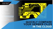
The moment you push your Gerbers to a manufacturer for a DFM inspection, it can be a nerve-wracking experience waiting for a response. Before you receive your working boards, there will likely be some back-and-forth communication before your board hits the fabrication line. When manufacturers and designers need to resolve problems in Gerber files before fabrication, it helps to have a Gerber compare utility. The newest version of Altium Designer now offers this feature through the Altium 365 platform, giving everyone visibility into changes to Gerbers before fabrication.

Blog
•
California Bets on Electric Cars and Plans to Ban Gasoline Car Sales by 2035
No matter how you might feel about renewable energy and associated environmental issues, electric vehicles are becoming more mainstream and will become the primary mode of transportation in the future. For the engineering community, what’s much more interesting is how our power distribution and management infrastructure can support this shift to massive increases in the use of electricity on the grid. So what’s the rub for PCB designers?
Blog
•
My Favorite Altium Designer Keyboard Shortcuts and Viewing Features
When you’re working through a complex PCB layout, it always helps to know the shortcuts you can use to stay productive. Altium Designer® keyboard shortcuts, and keyboard + mouse shortcuts, can help you easily walk through your PCB layout during design and as part of final checks during a design review. Here are some of my favorite keyboard shortcuts and viewing options that help me stay productive, and I hope they can do the same for you.

Blog
•
The IEEE P370 Standard for High Speed PCB Interconnects
High speed PCB interconnects have continued to remain an active challenge in modeling and simulation, particularly when dealing with broadband signals. The IEEE P370 standard is a step towards addressing the challenges faced by many designers in determining broadband S-parameters for high speed structures up to 50 GHz. Although this standard has been in the works since 2015, it finally passed board approval and appears as an active draft standard.

Blog
•
Class-D Amplifier Design and PCB Layout
Amplifiers can come in all shapes and sizes, depending on their bandwidth, power consumption, and many other factors. A Class-D amplifier design is normally used with high fidelity audio systems, and circuits for a Class-D amplifier are not too difficult to build in a schematic. If you’ve never worked with a Class-D amplifier or you’re looking for a fun audio project, follow along with this PCB layout.

Blog
•
DDR5 vs. DDR6: Here's What to Expect in RAM Modules
Modern digital systems throw the digital electronics textbooks out the window, and high-speed DDR memories are a perfect example of the paradigm shift that occurs when you jump into IC and PCB design. With DDR5 still being finalized, and DDR6 now being discussed, designers who are already comfortable with DDR4 will need to consider how their design practices should adjust to accommodate the constant doubling of data speeds in these high-speed memory technologies.



On-Demand Webinar
•
6月 12, 2025
Proactive Lifecycle Management: Preventing Obsolescence Before It Hits


On-Demand Webinar
•
4月 23, 2025
Collaborative Design Review: Ensuring Quality from Schematics to Supply Chain

On-Demand Webinar
•
4月 22, 2025
From Prototype to Production: Optimizing BOM Costs Without Compromising Quality with Part Analytics


On-Demand Webinar
•
4月 9, 2025
Component Selection in Altium Designer: Making Data-Driven Decisions with Data Integrations
On-Demand Webinar
•
3月 25, 2025
Unlocking the full potential of your design team with Altium's enterprise solution

On-Demand Webinar
•
1月 24, 2024
Discover How Altium Designer 24 Revolutionizes Team Dynamics in PCB Design


