Dec 26, 2021
Removed Connectivity and Footprint Changes in Schematic Compare
Copy Link
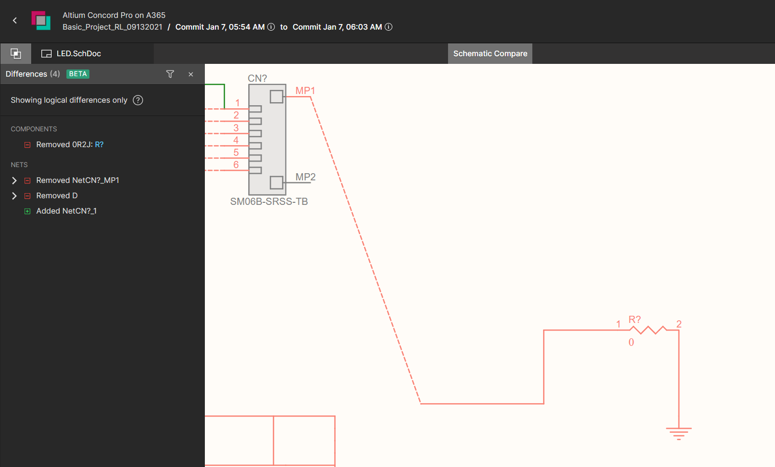
Now, with this update, the removed connectivity is displayed as a red dashed line between components or existing wires. To avoid visual clutter, the red dashed line is drawn as the shortest path between the previously connected objects.
The feature’s second update relates to the footprint changes of a component. The differences panel shows when such changes are detected by comparison.


Recommended Content
You can find more information on using Schematic Compare in Altium 365 by visiting the Getting Started User Guide - Schematic Compare.